


506471-01 Page 31 of 41Issue 1034
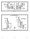
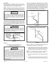
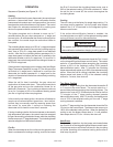
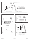
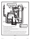
Sequence of Operation (see Figures 33 – 37)
Heating
On a call for heat from the room thermostat, the control board
performs a 1 second self check. Upon confirmation that the
pressure switch contacts are in an open position, the control
energizes the combustion blower on high speed. The control
then checks for adequate combustion air by making sure
the low-fire pressure switch contacts are closed.
The igniter energizes and is allowed to warm up for 7
seconds before the gas valve energizes on 1
st
stage and
burners ignite. 45 seconds after the control confirms ignition
has occurred, the control drops the combustion blower to
low speed.
The circulating blower ramps up to 50% of 1
st
stage heat speed
and operates at that speed for one minute (including ramp up
time), then at 75% of 1
st
stage heat speed for an additional
minute. After that, the circulating blower operates at full 1
st
stage heat speed until either the heat call is satisfied or the
thermostat initiates a call for 2
nd
stage heat. On a call for 2
nd
stage heat, the control energizes the circulating air blower on
full CFM 2
nd
stage heat.
If the automatic heat staging option is being used (see Single
Stage Thermostat Operation on page 27), the furnace does
not switch to 2
nd
stage heat in response to a call from the
thermostat but instead operates at 1
st
stage heat for the
duration of the selected time before automatically switching
to 2
nd
stage heat.
When the call for heat is satisfied, the gas valve and
combustion air blower shut down. The control board shuts
off the gas valve and runs the combustion blower for an
additional 15 seconds. The circulating air blower continues
to run for 2 minutes at 82% of the selected heating speed
(low fire or high fire) before ramping down.
In the event the unit loses ignition, the control will attempt to
recycle up to five times before it goes into a 1 hour lockout.
Lockout may be manually reset by removing power from
the control for more than 1 second or removing the
thermostat call for heat for more than 3 seconds.
If during a heating cycle the limit control senses an abnormally
high temperature and opens, the control board de-energizes
the gas valve and the combustion blower while the circulating
blower ramps up to 2
nd
stage heat speed. The circulating blower
remains energized until the limits are closed.
Fan On
When the thermostat is set for continuous fan operation and
there is no demand for heating or cooling, a call for fan closes
OPERATION
the R to G circuit and the circulating blower motor runs at
50% of the selected cooling CFM until switched off. When
the call for fan is turned off, the control de-energizes the
circulating blower.
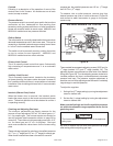
Cooling
The unit is set up at the factory for single stage cooling. For
two stage cooling operation, clip the jumper wire located
between the Y to Y2 terminals on the integrated ignition/
blower control board.
If the active dehumidification feature is enabled, the
circulating blower runs at 82% of the selected cooling speed
as long as there is a call for dehumidification.
Single Stage Cooling
A call for cooling from the thermostat closes the R to Y circuit
on the integrated ignition/blower control board. The control
waits for a 1-second delay before energizing the circulating
blower to 82% of the selected cooling CFM (passive
dehumidification mode). After 7.5 minutes, the circulating
blower automatically ramps up to 100% of the selected cooling
airflow. When the call for cooling is satisfied, the circulating
blower ramps back down to 82% of the selected cooling
airflow for 1 minute, then shuts off.
Two Stage Cooling
A call for 1
st
stage cooling from the thermostat closes the R
to Y circuit on the control board. The control waits for a 1-
second delay before energizing the circulating blower. The
blower motor runs at 57% of the selected air flow for the first
7.5 minutes of the 1
st
stage cooling demand (passive
dehumidification mode). After 7.5 minutes, the blower motor
runs at 70% of the selected cooling air flow until 1
st
stage
cooling demand is satisfied.
A call for 2
nd
stage cooling from the thermostat closes the R to
Y2 circuit on the control board. The blower motor ramps up to
100% of the selected cooling air flow. When the demand for
cooling is met, the blower ramps down to Y1 until satisfied,
then ramps down to 57% for 1 minute, then turns off.
Heat Pump
For heat pump operation, clip the jumper wire located below
the O terminal on the integrated ignition/blower control board.
In heat pump mode, a call for heat will result in the circulating
air blower operating at the selected cooling airflow after a
brief ramp-up period.
IMPORTANT
The system must not be in either the passive or active
dehumidification mode when charging a cooling system.