


0
5
10
15
20
25
30
35
40
45
50
55
60
degrees
advance
0
25
20
15
10
5
5
STEP 8
0
5
10
15
20
25
30
35
40
45
50
55
60
degrees
advance
0
25
20
15
10
5
5
0
5
10
15
20
25
30
35
40
45
50
55
60
degrees
advance
0
25
20
15
10
5
5
STEP 7
STEP 6
STEPS 1 & 2
6
7
TIMING ADVANCE
The following instructions apply only
to advance timing lights.
The following advance system checks are gen-
eral and may be used on most pre-emission
controlled vehicles. Note however, that many
vehicles have ignition and emission control sys-
tems, which may permit timing advance only
under certain operating conditions. It is there-
fore important on these vehicles to check your
vehicle service manual for specific instructions
on how to perform advance system checks.
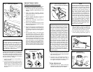
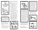
CENTRIFUGAL ADVANCE SYSTEM
Operational Test
1. Set the advance knob on the timing light to
the “0” degree position shown in Figure 7.
2. With the distributor vacuum line discon-
nected and plugged (Figure 5) and the
engine at curb idle, aim the timing light at
the timing marks, press the switch to oper-
ate the timing light and note the position of
the timing mark as shown in Figures 2 and
7. The timing mark or pointer should ap-
pear to be opposite one of the numbers
(initial timing) as shown.
3. Gradually increase the engine speed to
2500 RPM while observing the timing mark
position.
4. As the engine speed increases, the timing
mark should appear to move smoothly in the
opposite direction of engine rotation (the
spark advance direction). See Figure 6. As
engine speed is decreased, the timing mark
should appear to move smoothly back to the
initial timing mark noted in Step 2.
2
2
4
4
0
xya
xya
Fig. 6 -
Spark Advance Timing
TIMING
MARK
ROTATION
diator hose is hot). Adjust engine RPM to
the value specified by the vehicle manufac-
turer for timing purposes. If no value is
given, set the engine to curb idle.
4. Aim the timing light at the timing marks on
the engine and pull the trigger switch.
5. With the trigger switch pulled, and while
observing the timing marks, rotate the dis-
tributor slowly clockwise or counterclock-
wise as necessary to bring the timing into
factory specification. On most engines, a
change in timing will change engine RPM. If
this happens, reset the engine RPM as
indicated in Step 3 above and repeat Steps
4 and 5 until timing and RPM are within
factory specifications.
6. Shut off the engine. Tighten the distributor
hold down bolt securely.
7. Start the engine and recheck the timing. If it
drifted during the bolt tightening process,
readjust it as necessary.
8. Shut off the engine. Disconnect the timing
light leads in the reverse order from which
they were connected.
9. Reconnect any disconnected vacuum hoses
or electrical connectors which were discon-
nected as part of the engine’s preparation
for timing. Reset the engine’s idle speed if
necessary.
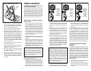
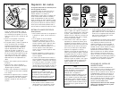
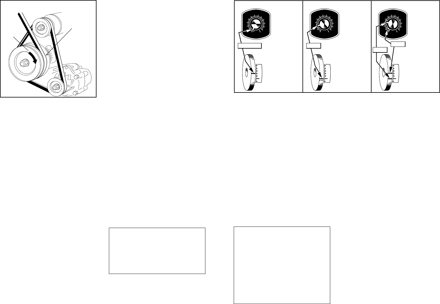
Fig. 8Fig. 7
Fig. 9
Calibration/Accuracy Test
5. Operate the engine at curb idle, direct the
timing light at the timing mark and turn the
control knob upscale until the timing mark
on the engine appears to be at “0” degrees.
(See Figure 8.) The number on the timing
light dial indicates the initial advance in
degrees, and should correspond to the
NOTE
Advance motion should be smooth. An
uneven or erratic advance motion may in-
dicate a defective centrifugal advance sys-
tem which should then be serviced as nec-
essary, according to the vehicle
manufacturer’s instructions.
NOTE
Some manufacturers give advance speci-
fications in distributor degrees and dis-
tributor RPM. Since the distributor rotates
at one half of engine or crankshaft speed,
the distributor specifications should be one
half of what is indicated on the advance
timing light dial. Vehicle test speed must
also be doubled if test speed is listed for
distributor RPM. It is therefore important to
know if the vehicle service manual is pre-
senting specifications in “engine” or “dis-
tributor” degrees and RPM.
8. Continue to turn the control knob until the
timing mark appears at the “0” degree (TDC)
mark on the engine. The reading reached
number obtained in Step 2. (This step does
not apply to those engines whose initial
timing is at or after Top Dead Center,
TDC).
6. Operate the engine at 2500 RPM or as
specified by the vehicle manufacturer for
the centrifugal advance check. The timing
mark may appear to move off scale, and
beyond the highest number. This may be
normal for the RPM being used and par-
ticular vehicle under test.
7. Direct the timing light at the timing mark and
turn the control knob until the timing mark
on the engine appears to return to the
initial timing position (as noted in Step 2
above). The reading reached on the timing
light dial now indicates the amount of cen-
trifugal advance in crankshaft or engine
degrees (Figure 9). Repeat the test as
required for various speeds as specified in
the vehicle service manual.
on the timing light dial now indicates the
total advance, that is, the initial advance
plus the centrifugal advance in degrees
(Figure 9).
If initial timing specification is after TDC, this
must be added to the timing light dial reading
to obtain total advance. (You may also rotate
the control knob further, to initial timing, thus
eliminating the need for calculation. Total ad-
vance will then be shown). Check the result
with manufacturer’s specifications. Repeat the
test as required for various speeds as speci-
fied in the vehicle service manual. If the read-
ing does not meet the manufacturer’s specifi-
cation, it may indicate a problem with the
centrifugal advance mechanism which should
then be corrected by repair or replacement.
VACUUM ADVANCE SYSTEM
CHECKS
Accurately checking the calibration of the
vacuum advance system requires not only the
advance timing light, but also a vacuum pump
with gauge such as described in the INTRO-
DUCTION at the beginning of this manual.
Most vehicle service manuals will indicate spe-
cific advance in degrees for a given vacuum in
inches of mercury. See your vehicle service
manual for specific procedures. As with the
centrifugal advance system checks, note
whether specifications are in distributor or
engine degrees.
9. Perform Steps 1-8 for the centrifugal ad-
vance system if not done as yet.
l0. Stop the engine and connect your exter
nal vacuum pump to the vacuum diaphragm
on the distributor or the vehicle’s on-board
computer.
READING
DAMPER
WHEEL ONLY
INITIAL
ADVANCE
IDLE RPM
VACUUM
HOSE
DISCONNECTED
READING
ADVANCE
TIMING LIGHT
DIAL
INITIAL
ADVANCE
IDLE RPM
VACUUM
HOSE
DISCONNECTED
READING
CENTRIFUGAL
ADVANCE AND
INITIAL
ADVANCE
CENTRIFUGAL
ADVANCE
2500 RPM
VACUUM
HOSE
DISCONNECTED