


4
5
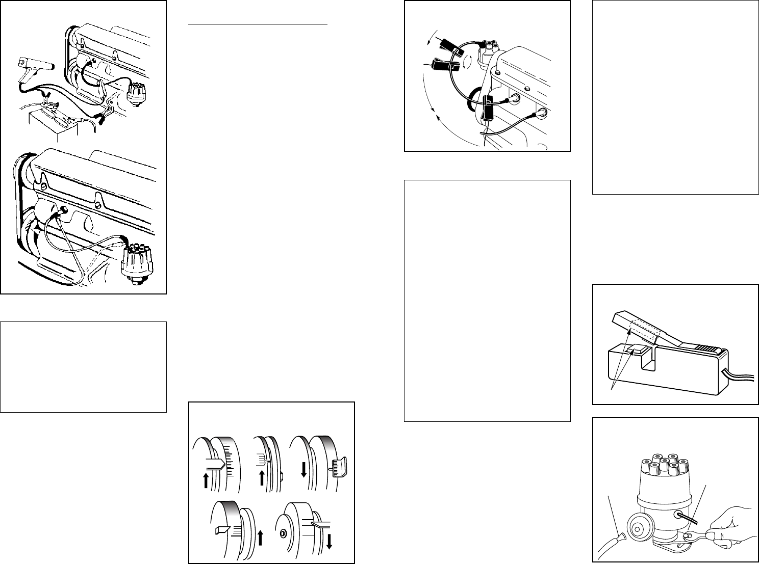
BLACK
RED
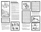
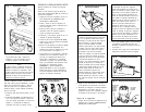
Fig. 1 - Hookup Diagram
Connect the spring adaptor and spark plug
lead between the spark plug (or distributor
cap) and the removed wire as shown in Figure
1. Route the timing light’s spark plug wire away
from the exhaust manifold and surrounding
hot areas to prevent damage.
4. Connect the RED clip to the positive (+)
battery terminal.
5. Connect the BLACK clip to a secure engine
ground such as the alternator bracket or
engine block. For safety reasons, do not
use the negative (-) battery terminal or fuel
system components as a ground connec-
tion point.
NOTE
On some engines, the distributor may be
mounted very close to the carburetor, or
fuel injection throttle body. Since this is an
area in which there may be gasoline vapors
present, it is adviseable on these engines
to remove the number one (1) spark plug
wire only at the spark plug end.
ENGINE TIMING CHECK
(Breaker point equipped engines only)
Check and, if necessary adjust dwell to specifi-
cation before proceeding with timing check.
1. Prepare the engine for timing as indicated
above in ENGINE PREPARATION FOR
TIMING.
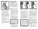
2. Clean, and chalk if necessary, both the
rotating and stationary timing marks on the
engine. See Figure 2.
3. Start the engine and allow it to warm to
normal operating temperature (upper ra-
diator hose is hot).
4. Check, and if necessary, adjust RPM to
specified timing speed.
5. When using an advance timing light, make
certain that the advance control is set fully
counterclockwise at “0”.
6. Aim the timing light at the crankshaft damper
(pulley) or transmission bell housing de-
pending on the location of the timing marks
on the engine under test. See Figures 1
and 2.
7. Pull the trigger switch on the timing light
and observe the location of the rotating
mark with respect to the stationary mark. If
timing is within the tolerance as specified
by the manufacturer (typically plus or mi-
nus 2 degrees) no adjustment is necessary
and the procedure is finished. If it is not
within specifications, proceed directly to
the
INITIAL TIMING ADJUSTMENT section
below. If the timing light multiple flashes or
flashes erratically on timing lights equipped
with an inductive pickup, see NOTE below.
Fig. 2 -
Various Timing Light
Configurations
TDC
UDC 1-6
16N
OP 1-6
O
A
3
6
10
0
DC
10
10
8. Shut off the engine. Disconnect the timing
light leads in the reverse order from which
they were connected.
9. Re-connect any disconnected hoses or
electrical connectors which were part of
the engine's preparation for timing. Reset
the engine’s idle speed if necessary.
Timing Adjustments
l. Make certain that the engine has been
prepared for timing as indicated above in
ENGINE PREPARATION FOR TIMING.
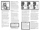
LOOSEN
HOLD-DOWN
BOLT
REMOVE
AND PLUG
VACUUM
HOSE IF
REQUIRED
Fig. 3 -
Positioning the Inductive
Pickup for Reliable Readings
NOTE
A defective ignition system may cause the
timing light to multiple flash or flash errati-
cally. Low output spark voltage or a defec-
tive ignition wire may be responsible. You
may be able to steady the flash by sliding
the inductive pickup along the plug wire to
a new location or reversing the inductive
pickup as shown in Figure 3. (This may
also help even with polarity sensitive pick-
ups). Solid copper ignition wires radiate
large amounts of radio frequency noise
through the air which may interfere with the
proper operation of the timing light and
other electronic equipment. Replace solid
copper ignition wire with resistance type
wire if only for the tests described in this
manual. Erratic flashing of the timing light
can also be caused by dirt or grease buildup
on the mating surfaces of the inductive
clamp. To maintain proper operation of the
clamp, clean and dry the inside clamp sur-
faces with a soft cloth when necessary as
shown in Figure 4.
NOTE
The following timing adjustment procedure
can be used on the majority of spark ig-
nited engines in use today. Both General
Motors and Ford Motor Company have
introduced and used special versions of
their common electronic ignition systems
which sense ignition directly from the
engine’s crankshaft via a crankshaft sen-
sor. These systems were introduced in the
late1970’s and were typically used only on
a few of the “high line” luxury passenger
cars. Timing is still checked with a timing
light in the standard manner, however,
timing adjustment is made at the crank-
shaft sensor, not by turning the distributor
as is normally done. See your vehicle serv-
ice manual for exact adjustment proce-
dures on this type system.
2. With the engine off, loosen the distributor
hold down bolt just enough so that the dis-
tributor can be turned freely. Do not loosen
the bolt beyond this point. See Figure 5.
3. Start the engine and allow it to warm to
normal operating temperature (upper ra-
CLEAN AND DRY HERE
Fig. 4 -
Cleaning the Inductive
Pickup
Fig. 5 -
Loosening the
Hold-Down Clamp