


SAFETY GUIDELINES
TO PREVENT ACCIDENTS THAT COULD RESULT IN SERIOUS INJURY
AND/OR DAMAGE TO YOUR VEHICLE OR TEST EQUIPMENT, CAREFULLY
FOLLOW THESE SAFETY RULES AND TEST PROCEDURES
2
3
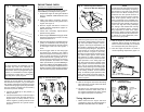
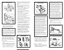
SAFETY EQUIPMENT
Fire Extinguisher
Never work on your car without having a
suitable fire extinguisher handy. A 5-lb or
larger CO
2
or dry chemical unit specified for
gasoline/chemical/electrical fires is recom-
mended.
Fireproof Container
Rags and flammable liquids should be stored
only in fireproof, closed metal containers. A
gasoline-soaked rag should be allowed to dry
thoroughly outdoors before being discarded.
Safety Goggles
We recommend wearing safety goggles when
working on your car, to protect your eyes from
battery acid, gasoline, and dust and dirt flying
off moving engine parts.
NOTE: Never look directly into the carburetor
throat while the engine is cranking or running,
as sudden backfire can cause burns.
LOOSE CLOTHING AND LONG HAIR
(MOVING PARTS)
Be very careful not to get your hands, hair or
clothes near any moving parts such as fan
blades, belts and pulleys or throttle and trans-
mission linkages. Never wear neckties or loose
clothing when working on your car.
JEWELRY
Never wear wrist watches, rings or other jew-
elry when working on your car. You’ll avoid
the possibility of catching on moving parts or
causing an electrical short circuit which could
shock or burn you.
VENTILATION
The carbon monoxide in exhaust gas is highly
toxic. To avoid asphyxiation, always operate
vehicle in a well-ventilated area. If vehicle is in
an enclosed area, exhaust should be routed
directly to the outside via leakproof exhaust
hose.
SETTING THE BRAKE
Make sure that your car is in Park or Neutral,
and that the parking brake is firmly set.
NOTE: Some vehicles have an automatic re-
lease on the parking brake when the gear shift
lever is removed from the PARK position. This
feature must be disabled when it is necessary
(for testing) to have the parking brake engaged
when in the DRIVE position. Refer to your
vehicle service manual for more information.
HOT SURFACES
Avoid contact with hot surfaces such as ex-
haust manifolds and pipes, mufflers (catalytic
converters), radiator and hoses. Never re-
move the radiator cap while the engine is hot,
as escaping coolant under pressure may seri-
ously burn you.
SMOKING AND OPEN FLAMES
Never smoke while working on your car. Gaso-
line vapor is highly flammable, and the gas
formed in a charging battery is explosive.
BATTERY
Do not lay tools or equipment on the battery.
Accidentally grounding the “HOT” battery ter-
minal can shock or burn you and damage
wiring, the battery or your tools and testers. Be
careful of contact with battery acid. It can burn
holes in your clothing and burn your skin or
eyes.
When operating any test instrument from an
auxiliary battery, connect a jumper wire be-
tween the negative terminal of the auxiliary
battery and ground on the vehicle under test.
When working in a garage or other enclosed
area, auxiliary battery should be located at
least 18 inches above the floor to minimize the
possibility of igniting gasoline vapors
HIGH VOLTAGE
High voltage — 30,000 to 50,000 volts — is
present in the ignition coil, distributor cap,
ignition wires and spark plugs. When handling
ignition wires while the engine is running, use
insulated pliers to avoid a shock. While not
lethal, a shock may cause you to jerk involun-
tarily and hurt yourself.
JACK
The jack supplied with the vehicle should be
used only for changing wheels. Never crawl
under car or run engine while vehicle is on a
jack.
missing, consult the vehicle service manual or
appropriate service literature for the engine
under test. It is important to note that prepara-
tion is specific to each engine.
TWELVE (12) VOLT POSITIVE (+)
GROUND ELECTRICAL SYSTEMS
Steps 4 and 5 of LEAD CONNECTIONS below
are revised to read as follows:
4. Connect the BLACK clip to the negative (-)
battery terminal.
5. Connect the RED clip to a secure engine
ground such as the alternator/generator
bracket or engine block. For safety rea-
sons, do not use the positive (+) battery
terminal or fuel system components as a
ground connection point.
All other instructions remain as listed.
SIX (6) VOLT ELECTRICAL
SYSTEMS
Follow the steps listed below to use your tim-
ing light on vehicles equipped with six (6) volt
electrical systems. A twelve (12) volt battery is
required. This can be any automotive, or mo-
torcycle battery.
1. Connect the RED clip from the timing light
to the positive (+) terminal of the twelve
(12) volt battery.
2. Connect the BLACK clip from the timing
light to the negative (-) terminal of the
twelve (12) volt battery.
3. Obtain a jumper wire (minimum wire size l8
AWG).
4. Connect one end of the jumper wire to the
negative (-) terminal of the twelve (12) volt
battery.
5. Connect the other end of the jumper wire to
a clean, secure ground on the vehicle un-
der test. The jumper wire must go to ground
on the vehicle regardless of whether the
vehicle is a positive (+) or negative (-)
ground system.
6. Connection to the number one (1) spark
plug and remaining procedures are the
same as described later in this manual.
ENGINE PREPARATION FOR
TIMING
In order for any engine to be base (initially)
timed correctly, it is important to carefully fol-
low the instructions as shown on the Vehicle
Emission Control label. This label is located
under the hood in the engine compartment.
Some typical locations are: the underside of
the hood, the fender well, a valve cover, or in
the area of the hood latch. If the label is
NOTE
The procedures outlined below instruct the
user to connect the spark plug pickup (direct
hookup or inductive clamp style) to the number
one (1) spark plug wire. This procedure is valid
for the majority of engines in use today. There
are however, some engines which are timed
using the “averaging” method. The most popu-
lar user of this method is General Motors
where it is recommended for some of there
smaller four (4) cylinder engines beginning in
1982. Your timing light has “average timing”
capability. The only change in hookup is that
instead of connecting the spark plug pickup to
the number one (1) spark plug wire, it is con-
nected to the coil tower wire, that is, the wire
between the ignition coil and the center of the
distributor cap. Consult your vehicle service
manual for exact procedures.
When using an advance timing light, note that
average timing is used only for initial or base
timing with the timing light’s advance control
set fully counterclockwise at “0”. Timing ad-
vance measurements must be made with the
inductive pickup clamped around the number
one (1) spark plug wire. Timing advance mea-
surements attempted with the inductive pickup
clamped around the coil tower wire will not
produce valid results.
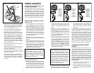
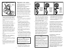
LEAD CONNECTIONS
1. Figure 1 shows the typical hookup proce-
dure for most applications. To insure safety,
follow the hookup sequence listed below.
2. Make sure the engine is OFF, and the
ignition key is OFF.
3. (Inductive Pickup equipped timing light)
Clamp the inductive pickup around the num-
ber one (1) spark plug wire. Do not allow the
inductive pickup to touch the exhaust mani-
fold or surrounding parts as these areas
become extremely hot and will damage the
inductive clamp.
(Direct connection equipped timing
light). Remove the number one (1) spark
wire from either the spark plug end, or the
distributor end, whichever is more conven-
ient, but without compromising safety. See
the NOTE below.