FX Series Programmable Controllers Points Of Technique 10
10-16
The maximum output volta
e (to the inverter) includin
ripple volta
e, can be found b
usin
the followin
equation:
Where:
e
m
= Maximum output volta
e
E
= pulse (square wave) output volta
e (see circuit on the previous pa
e)
t
= PWM pulse duration (see previous pa
e for reference)
T
0
= PWM c
cle time for pulse (see previous pa
e for reference)
The avera
e output volta
e (to the inverter) includin
ripple volta
e, can be found b
usin
the
followin
equation:
Where:
∆
e
= the volta
e value of the ripple
e
= ripple output volta
e
T
0
= PWM c
cle time for pulse
t
= PWM pulse duration
τ
= ripple circuit dela
See previous pa
e for references.
Operation
Once the s
stem confi
uration has been selected and the ripple circuit has been built to suit,
the motor speed ma
be varied b
ad
ustin
the value of 't' in the PWM instruction.
The lar
er the value of 't' the faster the motor speed will rotate. However, this should be
balanced with the knowled
e that the faster the output si
nal chan
es the
reater the ripple
volta
e will be. On the other hand a slowl
chan
in
output si
nal will have a more controlled,
et smaller ripple effect. The speed of the si
nal chan
e is determined b
the size of C1. A
lar
e capacitive value for C1 would
ive a smaller ripple effect as char
e is stored and
released over a lon
er time period.
The followin
characteristics were noticed when the identified circuit was tested
The PWM instruction had T
0
set to K50. The value for t was varied and also the load
impedance was varied to provide the followin
characteristics
raph (see over pa
e).
e
m
≈
E
t
T
0
T
0
- t
τ
∆
e
e
≈
T
0
τ
≤
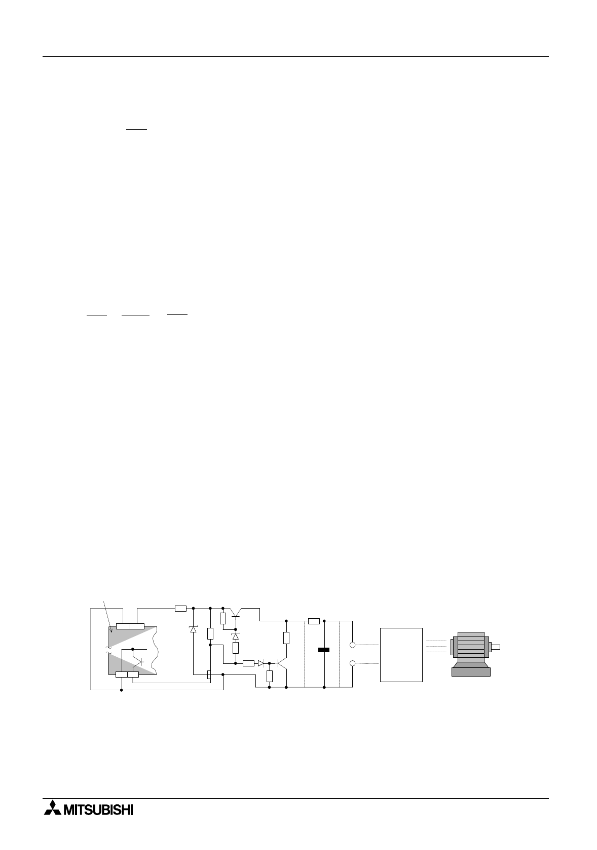
Y0
COM1
COM
24+
+
E
e
R1
R10
R7
R
4
R
5
R
6
R
9
R
8
Motor
Inverter
C1
5V
12V
Programmable
controller
Circuit confi
uration for a PLC with sink outputs.
The component values are the same as stated previousl


