Ch 2: Installation and Use of Devices
Hitachi PC VisionBase8450H/R Server 13
11. Power status lamp
Indicates the status of the power unit.
12. Power supply slots 1 to 2
Power units are installed in power slots 1 and 2.
13. Power supply slots 3 (optional)
You can install an optional power unit in power slot 3.
14. Error interface connector
Used to connect an Error interface.
15. PTL connector
Used to connect a PTL.
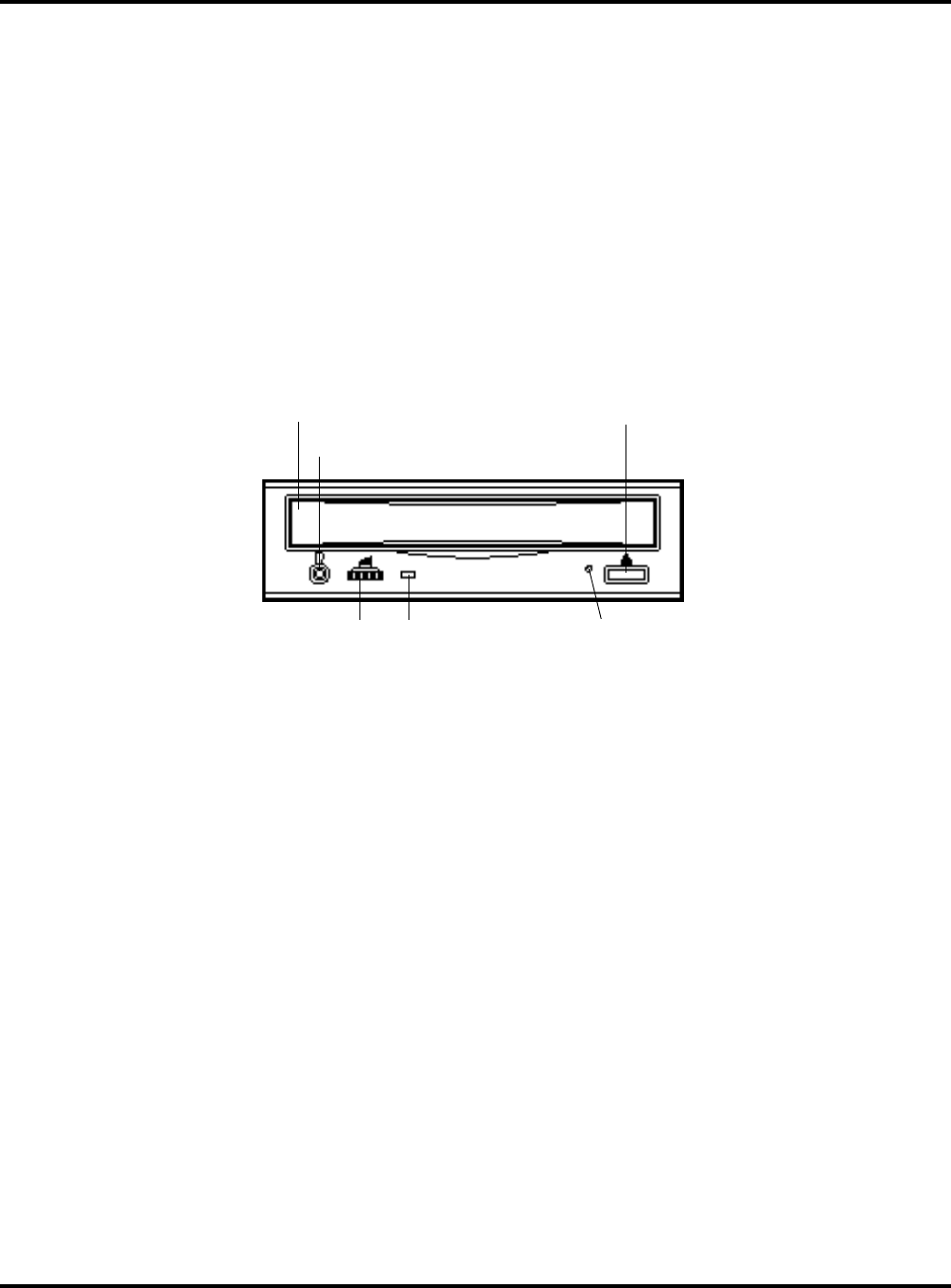
Internal CD-ROM (Standard)
1. Tray cover
The tray for carrying a CD-ROM is opened and closed here.
2. Open/close button
Used to open and close the tray.
NOTE: You can open or close the tray only while power is on. When a command has been issued to inhibit
button-initiated removal of a CD-ROM, you cannot use the open/close button to remove the CD-ROM.
3. Headphone jack
Used to connect the stereo pin plug for the headphone.
4. Headphone volume
Used to adjust the volume level of the headphone.
5. Busy indicator
Comes on while an internal CD-ROM is being started. Blinks during access.
6. Manual eject hole
Manual eject hole
Used to forcibly extract the CD-ROM when it cannot be extracted in an ordinary way because of a device failure.
Turn power off, wait about 15 seconds, then insert a thin rod into the hole. Push the rod about 35 mm further
from the point of first contact within the hole; the tray cover will open a little. Then use your hand to pull the
tray, and extract the CD-ROM.
The rod should be 50 mm or longer and stout, rod with a diameter of 1.0 to 1.8 mm. A straightened-out paper
clip is commonly used.
1. Tray cover
3. Headphone jack
4. Headphone volume 5. Busy indicator
6. Manual eject hole


