


YORK INTERNATIONAL
6
FORM 115.20-NOM3 (1006)
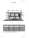
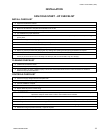
INSTALLATION
Many valve packages will not phys-
ically allow all components to fit
over an auxiliary drain pan. It is the
installers responsibility to ensure ad-
equate condensation prevention. The
installer must also ensure that there
is no condensate drippage onto elec-
trical components beneath insulated
components.
6. Avoid rapid quenching of solder joints, as this will
produce joints of inferior quality.
7. The valve package will not support the weight of
the connecting pipes. All pipes, which are connected
to the units, must be completely supported prior to
connection to the unit.
8. Provisions must be made for expansion and con-
traction of piping systems. All horizontal and
vertical risers, including runouts, must be able to
withstand significant movement with temperature
changes. Failure to do so will result in damage and
failure of piping, fittings and valves throughout the
building.
9. Never insulate the heads or motorized portion of
control valves. Damage can occur in the form of
excessive heat build up and interference to the
operation and moving parts will result.
10. All piping made in the field should be installed with
consideration of additional space for any electrical
routing that may be required.
11. Hydronic systems are not designed to hold pres-
surized air and should only be tested with water.
After the system has been proven leak free, all lines and
valve control packages must be insulated as specified
on the building plans.
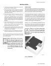
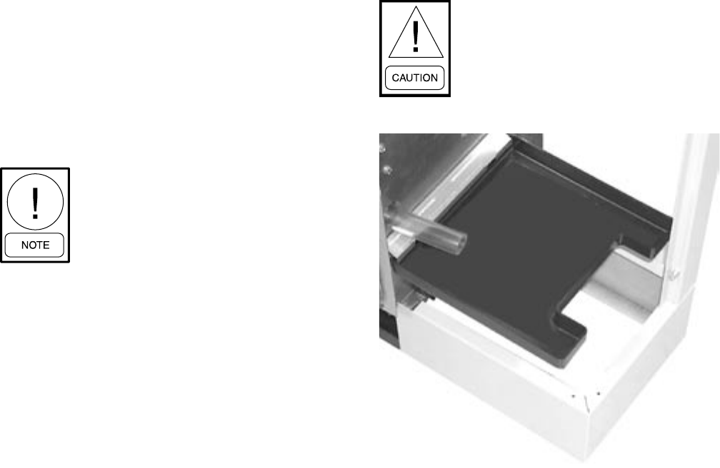
DRAIN PIPING
Drain line installation must adhere to all code requirements.
The plastic auxiliary drain pan is to be located under the
coil/valve connections supported by its mounting bracket.
Make sure drain pan is level for proper drainage.
The auxiliary drain pan connection is suitable to receive
a standard 3/4” PVC coupling or elbow. Route the
condensate line such that it will have adequate slope
from the pan to the drain. After condensate line has been
run, make sure plastic drain line from blower plate nipple
is routed to plastic auxiliary drain pan and plastic cap is
installed on other nipple on the blower plate.
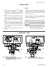
Note the 1-1/2” x 4-I/2” indentation in the plastic drain pan
(see Figure 6). This area is provided for the supply and
return runouts if they are brought up from below the pan.
All piping must be well insulated to prevent sweating.
Remove or cover the secondary drain
pan before soldering the supply and
return coil connections as hot solder
or the torch flame may damage the
pan.
00182VIP
FIG. 6 - DRAIN PAN