


YORK INTERNATIONAL
4
FORM 115.20-NOM3 (1006)
INSTALLATION
WIRING
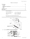
All wiring must comply with the local and national code
requirements. Units are provided with wiring diagrams
and nameplate data to provide information required for
necessary field wiring.
For power wiring a control box is provided on the
cabinet for connection of power supply and is located
on the opposite side of piping.
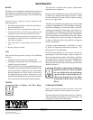
Any devices such as fan switches or
thermostats that have been furnished
by the factory for field installation
must be wired in strict accordance
with the wiring diagram that is sup-
plied with the unit. Failure to do so
could result in damage or injury.
4
VALVE
L (L1)
N (L2)
POWER
SUPPLY
GR D
1
2
3
4
1
2
3
TB1-1
TB1-2
TB3-1 TB3-2
TB2-2
TB2-4
TB2-3
TB1-4
TB2-1
HEAT
OFF
COOL
MED
HI
HEAT
COOL
LO
L1
TB3-3 TB2-5
MOTOR
TB1-1
TB1-2
TB3-1
TB2-2
TB3-2
TB2-3
TB2-4
TB1-4
TB2-1
TB3-3
MOTOR
OFF
COOL
MED
HI
LO
L
(L1)
N (L2)
L1
ON
VALVE
RISE
AQUASTAT
POWER
SUPPLY
GRD
HEAT
TB2-5
1
2
3
4
1
2
34
THERMISTOR
(UNIT-MTD)
(OPTIONAL)
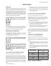
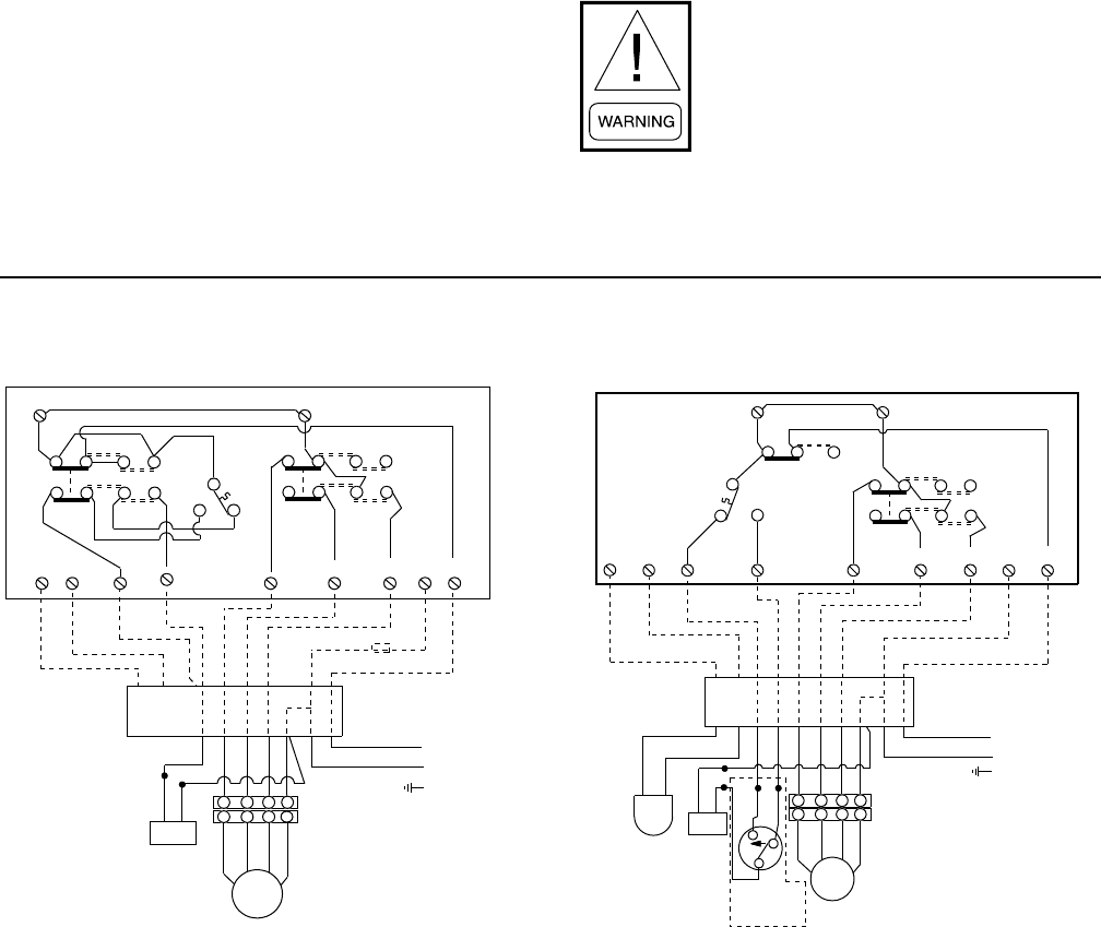
FIG. 2 - MANUAL CHANGEOVER,
CONTINUOUS FAN, T420 THERMOSTAT.
NO AQUASTAT LOCKOUT
2-PIPE HEAT / COOL
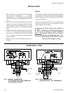
FIG. 3 - AUTO CHANGEOVER,
CONTINUOUS FAN, T421 THERMOSTAT.
LDO6889
LDO6890
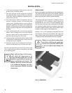
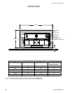
3. Mount the unit in its permanent location; making
sure it is level to insure proper drainage
and operation. 2 – ½” holes have been provided on
each end of the unit for securing the unit to the wall
studs.
4. After the drywall has been installed, recheck to
make sure the unit’s front panel is flush with the
exterior drywall surface. Shimming of the unit
may be required to get a seal between the unit and
panel.
5. Install the wall panel to the front of the unit using the
¼-20 x 1-1/2” long, painted, Phillips head screws
(4 on unit sizes 3,4,6 and 8; 6 on unit sizes 10 and
12). ¼” cage nuts are located in the slotted front
panel of the unit.
6. Remove the lower return air grille to get access to
the filter.