


5
YORK INTERNATIONAL
INSTALLATION
FORM 115.20-NOM3 (1006)
H
L (L1)
N (L2)
POWER
SUPPLY
GRD
1
2
3
4
1
2
3
4
TB1-1
TB1-2
TB3-1
TB3-2
TB2-2
TB2-4
TB2-3
TB1-4
TB2-1
HEAT
OFF
COOL
MED
HI
HEAT
COOL
LO
TB3-3
TB2-5
MOTOR
C
VALVES
THERMISTOR
(UNIT-MTD)
TB1-1
TB1-2
TB3-1
TB2-2
TB3-2
TB2-3
TB2-4
TB1-4
TB2-1
TB3-3
OFF
COOL
MED
HI LO
L1
ON
HEAT
TB2-5
H
L (L1)
N (L2)
POWER
SUPPLY
GRD
1
2
3
4
1
2
3
4
MOTOR
C
VALVES
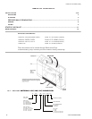
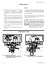
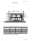
FIG. 4 - MANUAL CHANGEOVER,
CONTINUOUS FAN, T420 THERMOSTAT.
FIG. 5 - AUTO CHANGEOVER,
CONTINUOUS FAN, T421 THERMOSTAT.
4-PIPE HEAT / COOL
LDO6891
LDO6892
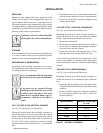
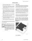
PIPING
These units employ a hydronic coil designed for use
with either hot or chilled water.
All piping must be adequately sized to meet the design
water flow requirements as specified for the specific
installation. Piping must be installed in accordance with
all applicable codes.
PIPE SIZES
• Tubing connections are 5/8" OD on all models.
• Manual air vents are provided standard on all
coils.
• All chilled water piping must be insulated to prevent
condensation.
PRECAUTIONS
1. Flush all field piping prior to connection to remove
all debris.
2. Use wet cotton rags to cool valve bodies when
soldering.
3. Open all valves (mid-way for hand valves, manually
open on motorized valves) prior to soldering.
4. When soldering to bronze or brass, heat the pip-
ing while in the socket/cup and begin introducing
the solder when the flux boils rapidly. Avoid direct
flame into the solder joint.
5. Heat can only be applied to the cup of the valve body
for a minimal time before damage occurs (even with
the use of wet rags).
Prior to connecting to the fan coil,
all external piping must be purged
of debris.
When connecting piping or valve
kits to fan coil units, do not bend or
reposition the coil header tubing for
alignment purposes. This could cause
a tubing fracture resulting in a water
leak when water pressure is applied
to the system.