


3
YORK INTERNATIONAL
INSTALLATION
FORM 115.20-NOM3 (1006)
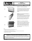
RECEIVING
Material in this shipment has been inspected at the
factory and released to the transportation agency in
good condition. When received, a visual inspection of
all cartons should be made immediately. Any evidence
of rough handling or apparent damage should be noted
on the delivery receipt and the material inspected in the
presence of the carrier's representative.
If damage is found, a claim should be
filed against the carrier immediately.
STORAGE
If the equipment is not to be immediately installed, store
it in a dry location with the motor protected against
moisture, dust, corrosion and physical damage.
PREPARE WALL FOR MOUNTING
Depending upon building construction, provisions
for mounting the unit must be made by the contractor
according to architects; drawings.
Unit must not be operated during
building construction due to excessive
airborne dust and debris. The units
must not be operated under any cir-
cumstances without an air filter in
place.
It is recommended that all mounting
holes be used for proper installation.
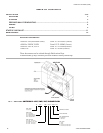
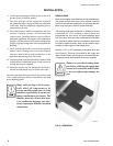
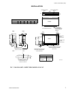
YVS / YVF UNIT STYLE (VERTICAL CABINET)
See Fig 7 for unit details and dimensions.
Mounting location must allow enough clearance to
permit the removal of screws that secure the cabinet
panels. After selecting the location for the unit, remove
the front panel. The front panel must be removed on
the YVS or YVF unit to gain access to the coil, drain
connections and electrical junction box. To accomplish
this:
1. Pull firmly on the lower cabinet door (each side)
until the cabinet releases from its friction fastener.
2. Proceed to lift the door assembly straight up and
off the cabinet frame.
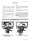
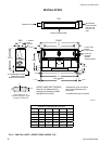
YVC UNIT STYLE ( VERTICAL CONCEALED)
See Fig 8 for unit details and dimensions.
Mounting location must allow enough clearance to
permit the removal of screws that secure the cabinet
panels. After selecting the location for the unit:
1. Remove the front panel.
2. Position the unit in its permanent location, making
sure it is level to insure proper drainage and opera-
tion, and secure the unit in place.
3. Secure the unit to the wall using the four, 1/2 inch
holes provided (two on each end of the unit).
Access must be provided for servicing the unit. If this
access is provided by a removable panel, ample space
must be allowed for access to electrical and plumbing
controls.
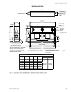
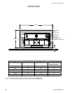
YWC UNIT STYLE (RECESSED WALL)
See Fig 9 for unit details and dimensions.
Mounting location must allow enough clearance to
permit the removal of all mechanical parts within the
unit.
1. Frame the unit as required so the front panel of the
wall unit will be flush with the drywall surface when
installed.
2. Frame around the perimeter of the unit as required
for securing the drywall. See Table 1 below for
drywall openings.
MODEL NUMBER DRYWALL CUTOUT DIM
HT x WD
3YWC 28 x 42
4YWC 28 x 50
6YWC 28 x 58
8YWC 28 x 66
10YWC 28 x 74
12YWC 28 x 82
TABLE 1 – DRYWALL OPENINGS