


YORK INTERNATIONAL
14
YORK INTERNATIONAL
15
FORM 150.63-EG1
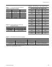
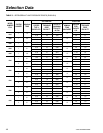
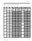
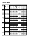
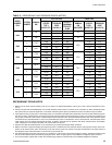
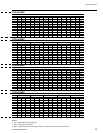
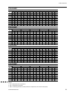
TABLE 5 – REFRIGERANT LINE PRESSURE DROPS (METRIC)
MODEL
NUMBER
YCUL
SYSTEM
NUMBER
1
NOMINAL
KW
SUCTION LINE LIQUID LINE
COPPER
TYPE L
INCHES O.D.
2
PRESSURE
DROP
kPa/30.5 m
VELOCITY
@NOMINAL
CAPACITY
IN M/S
4
NOMINAL
KW
UNLOADED
COPPER
TYPE L
INCHES O.D.
3
PRESSURE
DROP
kPa/30.5 m
0090
1 158
2-1/8 33.8 20.6
53
1-1/8 30.3
5
2-5/8 11.7 13.7 1-3/8 11.7
2 158
2-1/8 33.8 20.6
53
1-1/8 30.3
5
2-5/8 11.7 13.8 1-3/8 11.7
0096
1 175.7
2 5/8 14.5 914
87.9
1 1/8 37.2
3 1/8 6.2 671 1 3/8 14.5
2 144.1
2 1/8 28.3 1125 1 1/8 25.5
2 5/8 9.7 750 1 3/8 9.7
0100
1 172.2
2 5/8 13.8 896
87.9
1 1/8 35.9
3 1/8 6.2 657 1 3/8 13.8
2 172.2
2 5/8 13.8 896 1 1/8 35.9
3 1/8 6.2 657 1 3/8 13.8
0106
1 207.4
2 5/8 19.3 1079
70.3
1 1/8 50.3
3 18 8.3 791 1 3/8 19.3
2 175.7
2 5/8 14.5 914 1 1/8 37.2
5
3 1/8
6.2 671 1 3/8 14.5
0120
1 214.4
2 5/8 20.7 1116
70.3
1 1/8 53.8
5
3 1/8
9.0 818 1 3/8 20.7
2 214.4
2 5/8 20.7 1116 1 1/8 53.8
5
3 1/8
9.0 818 1 3/8 20.7
0130
1 260.1
2 5/8 29.6 1353
87.9
1 3/8 29.6
3 1/8 13.1 992 1 5/8 11.0
2 210.9
2 5/8 20.0 1097 1 1/8 52.4
3 1/8 9.0 805 1 38 20.0
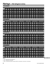
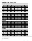
REFRIGERANT PIPING NOTES
1. Based on R-22 at the nominal capacity of the unit or system, an ambient temperature of 95°F (35°C) and a suction temperature of 45°F
(7.2°C).
2. Suction line sizes were calculated based on a nominal maximum pressure drop to 3 PSI/100 ft. (20.7 kPa/30.5 m). When calculating suction
line pressure drop for a specic application, it should be noted that system capacity decreases as suction line pressure drop increases.
3. Liquid pressure drop (or gain) due to a vertical liquid line is not included in the tables and must be taken into account when determining pres-
sure drop (or gain) of the liquid line. The nominal value that must be included in the liquid line loss (or gain) is .5 PSI/foot (3.4 kPa/30 cm) of
rise (or gain). To ensure a solid column of liquid refrigerant to the expansion valve, the total maximum pressure drop of the liquid line should
not exceed 40 PSI (276 kPa) based on 15°F (8.3°C) subcooled liquid. Vapor in the liquid line, even in small amounts, will measurably reduce
valve capacity and poor system performance will result. In addition, pressure loss for strainers, lter driers, solenoid valves, and isolation
valve or ttings are not included in this table, and must be taken into account.
4. Nominal Tons (KW) Unloaded is based on one compressor (per system) operating at design conditions.
5. Based on minimum compressor staging for the given pipe size, a double suction riser should be used to ensure proper oil return to the com-
pressor on all vertical suction risers. Oil returning up the riser moves up the inner surface of the pipe and depends on the mass velocity of
the refrigerant vapor at the wall surface to move the oil up the vertical rise.
6. Hot gas bypass lines are typically 7/8" for lines up to 40 feet and 1-1/8" for lines over 40 feet in length (12 meters). The eld connections sizes
are 7/8" for the optional factory mounted hot gas bypass valve. Note: Hot gas bypass is only available for refrigerant system number 1.
7. For more information, please refer to either the York DX Piping Guide (form 050.40-ES2) or the ASHRAE Refrigertion Handbook.