


YORK INTERNATIONAL
10
YORK INTERNATIONAL
11
FORM 150.63-EG1
Selection Data
REFRIGERANT PIPING
General – When the unit has been located in its nal
position, the unit piping may be connected. Normal instal-
lation precautions should be observed in order to receive
maximum operating efciencies. System piping should
conform to the York DX piping guide form 050.40-ES2 or
ASHRAE refrigeration handbook guidelines. All piping
design and installation is the responsibility of the user.
YORK ASSUMES NO WARRANTY RESPONSIBILITY
FOR SYSTEM OPERATION OR FAILURES DUE TO
IMPROPER PIPING OR PIPING DESIGN.
Filter driers and sight glasses are shipped loose for eld
installation on each refrigerant circuit. Field refrigerant
piping can be connected to the condensing unit.
All expansion valves, liquid line solenoid valves, refrig-
erant and refrigerant piping are supplied and installed
by others.
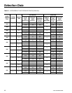
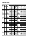
Table 4 lists refrigerant line connections sizes per unit
model number.
REFRIGERANT LINE SIZING
Refrigerant piping systems must be designed to provide
practical line sizes without excessive pressure drops,
prevent compressor oil from being “trapped” in the refrig-
erant piping, and ensure proper ow of liquid refrigerant
to the thermal expansion valve. Considerations should
be give to:
1) Suction line pressure drop due to refrigerant ow.
2) Suction line refrigerant velocity for oil return.
3) Liquid line pressure drop due to refrigerant ow.
4) Liquid line pressure drop (or gain) due to vertical rise
of the liquid line.
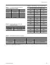
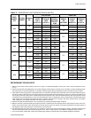
Table 5 provides the pressure drops for given pipe sizes
for both liquid and suction lines. The pressure drops
given are per 100 equivalent ft. (30.5 m) of refrigerant
piping. These friction losses do not include any allow-
ances for strainer, lter drier, solenoid valve, isolation
valve or ttings
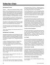
Nominal pressure drop for solenoids, sight glass, and
driers are shown in Table 2.
Table 1 includes approximate equivalent lengths for
copper ttings.
To ensure a solid column of liquid refrigerant to the expan-
sion valve, the total liquid line pressure drop should
never exceed 40 psi (276 kPa). Refrigerant vapor in
the liquid line will measurably reduce valve capacity and
poor system performance can be expected.
To allow adequate oil return to the compressor, suction
risers should be sized for a minimum of 1000 FPM (5.08
m/s) while the system is operating at minimum capacity
to ensure oil return up the suction riser. Refer to Table 5
under column labeled Nominal Tons (KW) Unloaded.
Evaporator Below Condensing Unit
On a system where the evaporator is located below the
condensing unit, the suction line must be sized for both
pressure drop and oil return. In some cases a double
suction riser must be installed to ensure reliable oil return
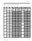
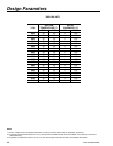
at reduced loads. Table 3 indicates when a double suc-
tion riser should be used for listed pipe sizes to provide
adequate oil return at reduced loads. The calculated
information was based on maintaining a minimum of
1000 fpm (5.08 m/s) refrigerant vapor velocity.
Condenser Below Evaporator
When the condensing unit is located below the evapora-
tor, the liquid line must be designed for both friction loss
and static head loss due the vertical rise. The value of
static head loss of 5 PSI/ft.(3.4 kPa/30 cm) must be
added to the friction loss pressure drop in addition to all
pressure drops due to driers, valves, etc.
OIL TRAPS
All horizontal suction lines should be pitched at least 1/4"
per foot (2 cm/m) in the direction of the refrigerant ow
to aid in the return of oil to the compressor. All suction
lines with a vertical rise exceeding 3 feet (.91 meters)
should have a “P” trap at the bottom and top of the riser.
Suction lines with a vertical rise exceeding 25 feet (7.6
meters) should be trapped every 15 feet (4.6 meters).
REFRIGERANT CHARGE
The condensing unit is charged with a dry nitrogen hold-
ing charge. The remaining operating charge for the con-
densing unit, evaporator coil, and refrigerant piping must
be weighed in after all refrigerant piping is installed, leak
checked, and evacuated. Final adjustment of refrigerant
charge should be veried by subcooling values (refer to
section on Pre-Startup for checking subcooling).
REFRIGERANT PIPING REFERENCE
For more details, refer to ASHRAE Refrigeration Hand-
book, Chapter 2.