


262675-UIM-A-0806
6 Unitary Products Group
NOTE: All wiring must comply with local and national electrical code
requirements. Read and heed all unit caution labels.
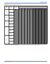
NOTE: It is possible to vary the amount of electric heat turned on during
the defrost cycle of a heat pump. Standard wiring will only bring on the
first stage of electric heat during defrost. See Heat Output and Limit
Connections and Table 6 for additional information on heat during
defrost cycle.
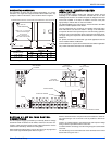
The low voltage connections may be connected to the screw terminals
or the quick connect terminals. The screw terminals and the quick con-
nect terminals are physically connected on the control board.
HUMIDITY SWITCH INPUT
The air handler control is designed to work with a humidity control that
closes when the humidity is below the set-point. The control is open
when the humidity is above the set-point. This humidity control may be
referred to as a humidistat or a dehumidistat.
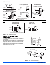
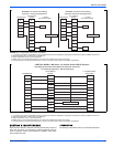
The humidity switch controls both humidification and de-humidification
operation of the control. The control provides humidification using the
HUM OUT relay output and de-humidification by lowering the blower
speed. This is accomplished using the LOW FAN output and a field
installed two-speed fan relay kit for non-variable speed models and the
de-humidification input of the motor for variable speed models. The
humidity switch should be connected to the R and HUM terminals of the
control. See Figures 10 & 11.
SECTION VI: REQUIRED CONTROL
SET-UP
IMPORTANT: The following steps must be taken at the time of installa-
tion to insure proper system operation.
1. Consult system wiring diagram to determine proper thermostat
wiring for your system.
2. If heat kit is installed, change HEAT ENABLE jumper from NO
HEAT to HEAT position.
3. If a humidstat is installed, change HUM STAT jumper from NO to
YES.
4. Set the MODE jumper to A/C (Air Conditioner) or HP (Heat Pump)
position depending on the outdoor unit included with the system.
FUNCTIONALITY AND OPERATION
Jumper Positions
Heat Enable Jumper
The HEAT ENABLE jumper configures the control for heat kit operation.
The jumper must be in the HEAT position if a heat kit is installed with
the air handler.
With the jumper in the NO HEAT position, the control will not energize
the heat relay outputs or sense the limit switch input.
If the jumper is not present, the control will operate as if the jumper is in
the HEAT position. If the jumper is not present and a heat kit is not
present, the control will sense an open limit condition and the blower
will run continuously.
Hum Stat Jumper
The HUM STAT jumper configures the control to monitor the humidity
switch input. With the jumper in the NO position, the control will ener-
gize the HUM terminal with 24 VAC continually. With the jumper in the
YES position, the control will monitor the HUM input to control the HUM
OUT output to control an external humidifier.
If the jumper is not present, the control will operate as if the jumper is in
the YES position.
Mode Jumper
The MODE jumper configures the control to operate properly with an air
conditioner (AC position) or heat pump (HP position). With the jumper in
the AC position, the control will energize the O terminal with 24 VAC
continually. With the jumper in the HP position, the O input signal is
received from the room thermostat.
If the jumper is not present, the control will operate as if the jumper is in
the HP position.
SPARE Jumper
The control includes a spare jumper that can be used if a jumper is lost.
The SPARE jumper does not have any effect on the operation of the
control.
Status and Fault Codes
The control includes an LED that displays status and fault codes. These
codes are shown in Table 3. The control will display the fault codes until
power is removed from the control or the fault condition is no longer
present.
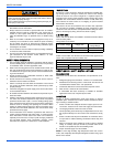
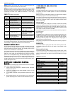
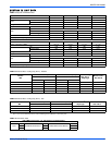
TABLE 2:
Low Voltage Connections
Terminal Signal Comment
R 24 VAC power (fused)
G Continuous Fan operation
Y/Y2
Second or full stage
compressor operation
Y1
First stage compressor
operation
Not used with outdoor units
having one stage compressors.
W2 Second stage heat operation
W1 First stage heat operation
O Reversing valve operation
24 VAC will be present at this
terminal when the MODE
jumper is in the AC position.
This is normal.
HUM Humidity switch input
24 VAC will be present at this
terminal when the HUM STAT
jumper is in the NO position.
This is normal.
X/L
Connection point for
heat pump fault indicator
This terminal is a connection
point only and does not affect
air handler control operation.
COM 24 VAC common
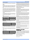
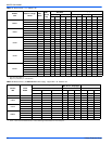
TABLE 3:
Fault Codes
Fault or Status Condition
LED1 (RED)
Flash Code
Status
No power to control OFF
Normal operation 2s ON / 2s OFF
Control in test mode Rapid Flash
Control failure ON
Limit Faults
Limit switch currently open (not in lockout) 1
Multiple limit openings with no call for heat 2
Multiple limit openings during one call for heat 3
Single long duration limit opening 4
Multiple long duration limit openings 5
Fan failure 6
Wiring Related Faults
Simultaneous call for heating and cooling 7
Internal Control Faults
Control recovered from internal event 9