


262675-UIM-A-0806
4 Unitary Products Group
DUCT CONNECTORS
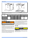
Air supply and return may be handled in one of several ways best
suited to the installation. See Figure 3 for dimensions for duct inlet and
outlet connections.
The vast majority of problems encountered with combination heating
and cooling systems can be linked to improperly designed or installed
duct systems. It is therefore highly important to the success of an instal-
lation that the duct system be properly designed and installed.
Use flexible duct collars to minimize the transmission of vibration/noise
into the conditioned space. If electric heat is used, non-flammable
material must be used.
Where return air duct is short, or where sound may be a problem,
sound absorbing glass fiber should be used inside the duct. Insulation
of duct work is a must where it runs through an unheated space during
the heating season or through an uncooled space during the cooling
season. The use of a vapor barrier is recommended to prevent absorp-
tion of moisture from the surrounding air into the insulation.
The supply air duct should be properly sized by use of a transition to
match unit opening. All ducts should be suspended using flexible hang-
ers and never fastened directly to the structure. This unit is not
designed for non-ducted (freeblow) applications. Size outlet plenum or
transition to discharge opening sizes shown in Figure 3.
Duct work should be fabricated and installed in accordance with local
and/or national codes. This includes the standards of the National Fire
Protection Association for Installation of Air-Conditioning and Ventilat-
ing Systems, NFPA No. 90B.
AIR FILTERS
Air filters and filter racks must be field supplied.
.
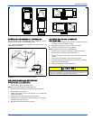
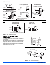
SUSPENSION KITS
A suspension kit is available. Models 1BH0601 (unit size 018-060) is
designed specifically for the units contained in this instruction (upflow
application only). For installation of these accessory kits, see the
instructions packed with the kit.
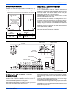
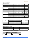
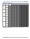
FIGURE 3: Dimensions & Duct Connection Dimensions
J
10-3/8”
E
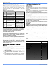
CIRCUIT BREAKER
PANEL
BOTTOM INLET
DIMENSIONS
B
A
K
TOP OUTLET
DIMENSIONS
D
22”
20-1/2”
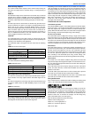
TABLE 1:
Dimensions
MA
MODELS
Dimensions
Wiring Knockouts
1
ABDEJK
Height Width Power Control
08B
25
17-1/2 16-1/2 14-19/32
7/8” (1/2”)
1 3/8” (1”)
1 23/32” (1 1/4”)
7/8” (1/2”)
12B 17-1/2 16-1/2 14-19/32
14D 24-1/2 23-1/2 21-19/32
16C 21 20 18-3/32
20D 24-1/2 23-1/2 21-19/32
1. Actual size (Conduit size).
Use 1/2" screws to connect ductwork to bottom of unit. Longer
screws will pierce the drain pan and cause leakage. If pilot holes
are drilled, drill only though field duct and unit bottom flange.
Equipment should never be operated without filters.