


262675-UIM-A-0806
Unitary Products Group 5
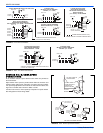
HORIZONTAL SUSPENSION
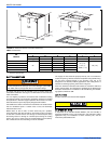
For suspension of these units in horizontal applications, it is recom-
mended to use angle steel support brackets with threaded rods, sup-
porting the units from the bottom, at the locations shown in Figure 4.
SECTION IV: ELECTRIC HEATER
INSTALLATION
If the air handler requires electric heat, install the electric heat kit
according to the installation instructions included with the kit. After
installing the kit, mark the air handler nameplate to designate the heater
kit that was installed. If no heater is installed, mark the name plate
appropriately to indicate that no heat kit is installed.
The HEAT ENABLE jumper (See Figure 5) must be moved to the HEAT
position to enable operation of the heater.
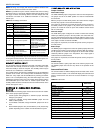
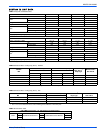
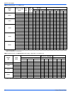
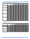
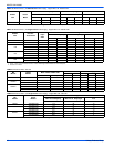
Use only 4HK heater kits, as listed on Air Handler name plate and in
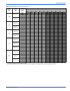
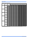
these Instructions. Use data from Tables 11 through 18 for information
on required minimum motor speed tap to be used for heating operation,
maximum over-current protection device required and minimum electri-
cal supply wiring size required for listed combination of Air Handler and
Heater Kit.
For Upflow, Downflow and Horizontal right hand applications the kits
can be installed without modification.
Field modification is required for Horizontal left-hand airflow application
only. Follow instructions with heater for modification.
SECTION V: LOW VOLTAGE CONTROL
CONNECTIONS
The 24 volt power supply is provided by an internally wired low voltage
transformer which is standard on all models, However, if the unit is con-
nected to a 208 volt power supply, the low voltage transformer must be
rewired to the 208 volt tap. See the unit wiring label.
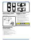
Field supplied low voltage wiring can exit the unit on the top right hand
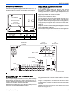
corner or the right hand side panel. Refer to Figure 3.
Remove desired knockout and pierce foil faced insulation to allow wir-
ing to pass through. Use as small of a hole as possible to minimize air
leakage.
Install a 7/8” plastic bushing in the selected hole and keep low voltage
wiring as short as possible inside the control box.
To further minimize air leakage, seal the wiring entry point at the outside
of the unit.
The field wiring is to be connected at the screw terminals of the control
board. Refer to Figures 10 & 11.
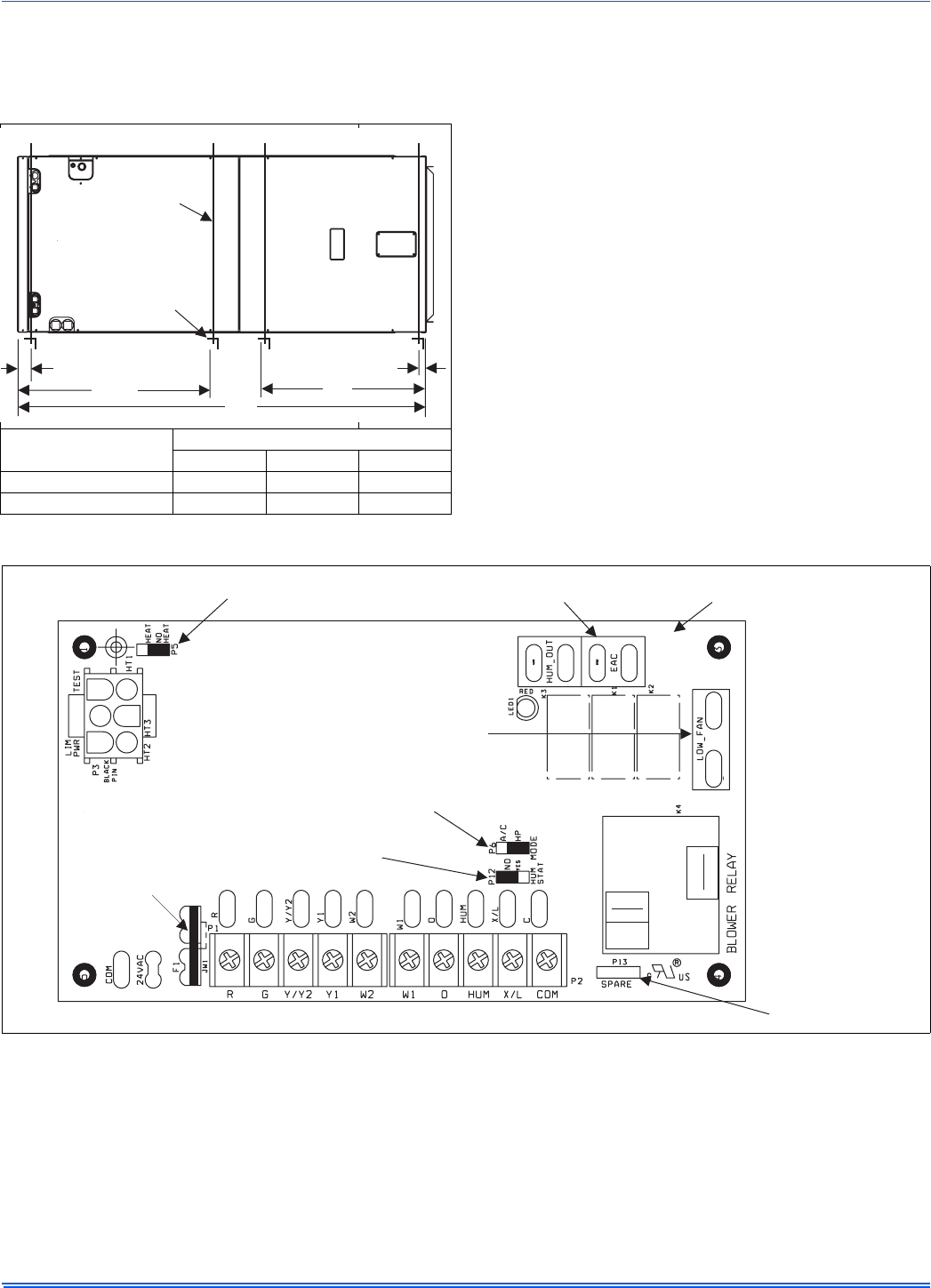
Units
(Nominal Tons)
Dimension
WW XX YY
1-1/2 - 3 Ton 16” 48” 22”
3-1/2 - 5 Ton 24” 53” - 58” 22”
FIGURE 4: Typical Horizontal Installation
WW
XX
SUSPENSION SUPPORT LOCATIONS FOR HORIZONTALAPPLICATIONS
2
1-1/2
MIN. 1-1/2” x 1-1/2” Angle
Recommended length
26” minimum
with 2” clearance on
both sides of Air Handler
MIN. 3/8”
THREADED ROD
YY
FIGURE 5: Control Board
HEAT ENABLE
JUMPER
HUM OUT
RELAY OUTPUT
EAC
RELAY OUTPUT
LOW FAN
RELAY OUTPUT
SPARE JUMPER
HUM STAT JUMPER
MODE JUMPER
FUSE