


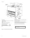
Before brazing the refrigerant lines tothese connections,
remove the short panel from the unit frame and slide it
(along with the grommets) onto the refrigerant lines. Af
-
ter the brazed joints have cooled, slide the panel back
into place and secure it to the unit frame.
NOTE: These units can only be piped from one side of
the unit.
EXPANSION VALVE BULB
On KEU090 units the expansion valve bulb must be fas
-
tened in a 4 o'clock position to the suction line outside the
cabinet after the piping connections have been made.
On KEU120 units fasten the expansion valve bulb on the
suction header 8" (203mm) below the top of the header
and adjacent to the coil.
Use the clamps provided with the valve to secure the
bulb in position.
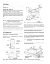
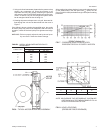
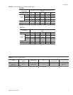
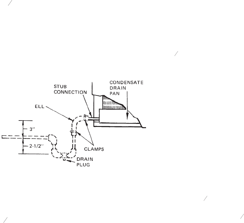
DRAIN CONNECTION
The drain line MUST be trapped because the coil is lo
-
cated on the negative side of the supply air blower. It
must also be protected from freezing temperatures.
A
7
8
" (22.2mm) OD stub connection is provided within
the cabinet on both ends of the condensate drain pan for
either left hand or right hand pipingconnections. Refer to
Figure 5 for recommended drain piping.
The drain line is located on the same end of the coil sec-
tion as the refrigerant connections. The line should be in-
sulated where moisture drippage will be objectionable or
cause damage to the area. Seal the unused drain con-
nection with a suitable mastic.
The 3" (76mm) dimension must equal or exceed the
negative static pressure developed by the supply air
blower. If it does not, condensate will not drain properly
and may overflowthe drain pan. The trap mustbe atleast
2
1
2
" (63mm) deep to maintain a water seal underall oper
-
ating conditions, especially during blower start-up.
NOTE: Refer to Figure 9 for minimum clearance require
-
ments.
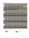
SUPPLY AIR BLOWER ADJUSTMENT
The RPM of the supply air blower will depend on the re
-
quired airflow, the unit accessories and the static resis
-
tances of both the supply and the return air duct
systems. With this information, the RPM for the supply
air blower can be determined from the blower perform
-
ance in Table 4.
Knowing the required blower RPM and the blower motor HP,
the setting (turns open) for the supply air motor pulley can be
determined from Table 3.
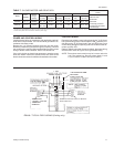
Each motor pulley has:
1. A threaded barrel with two flats (or notched recesses) 180
degrees apart.
2. A movable flange with one set screw.
After the movable flange has been rotated to the proper
number of “turns open”, the set screw should be tight
-
ened against the flat on the barrel to lock the movable
flange in place. If the pulley includes a locking collar, the
locking collar must be loosened to adjust the setting of
the movable flange.
Note the following:
1. The supply airflow must be within the limitations shown in
Table 1.
2. All pulleys can be adjusted in half-turn increments.
3. The tension on the belt should be adjusted for a deflection
of
3
16
" (5mm) per foot (305mm) of belt span with an applied
force of approximately 3 lbs (1.4kg). This adjustment is
made by moving the blower motor mounting plate. Refer to
Figure 6. Turning the adjustment bolt (B) moves the motor
mounting plate up or down. Note - Never loosen the two
nuts (C). Four hex nuts (A) have to be loosed to move the
mounting plate and retightened after the mounting plate
has been moved to the proper position.
4. All pulleys are factory aligned.
5. All supply air motor pulleys are factory set at three “turns
open.”
After the supply air blower motor is operating, adjust the
resistances in both the supply and the return duct sys
-
tems to balance the air distribution throughout the condi
-
tioned space. The job specifications may require that
this balancing bedone bysomeone otherthan theequip
-
ment installer.
To check thesupply airairflow afterthe theinitial balancinghas
been completed:
1. Drill two holes
5
16
" (8mm) dia. in the side panel as shown in
Figure 8.
2. Insert at least 8" (200mm) of
1
4
" (6.3mm) O.D. tubing into
each of these holes for sufficient penetration into the air
flow on both sides of the evaporator coil.
NOTE: The tubes must be inserted and held in a position per
-
pendicular to the air flow so that velocity pressure will
not affect the static pressure reading.
6 Unitary Products Group
550.39-N4YI
FIG. 5 - RECOMMENDED DRAIN PIPING
(64)
(76)