


Unitary Products Group 11
550.39-N4YI
MOTOR SPECIFICA
-
TIONS
•1450 RPM
•380/415-3-50
•Solid base
•56 Frame
•Inherently protected
Permanently lubricated
ball bearings
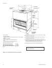
POWER AND CONTROL WIRING
Install electrical wiring in accordance with applicable national,
local and municipal codes. The unit should be grounded in ac
-
cordance with these codes.
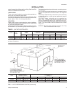
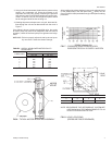
Remove the 1
3
8
" (35mm) knockout from the unit rear panel.
Route the power wiring conduit through this opening. Connect
the conduit to the required field-supplied fitting and the power
wiring to blower motor contactor 10M in unit control box.
If the unit includes an electric heat accessory, route the power
wires into heater control box instead of the unit. Refer to the
electricheat instructions for additional installation information.
Model
Motor
(HP/kW)*
Blower
Range
(RPM)
Adjustable Motor Pulley Fixed Blower Pulley Belt
Pitch Dia
(In./mm)
Bore
(In./mm)
Pich Dia.
(In./mm)
Bore
(In./mm)
Designa
-
tion
Pitch Lg.
(In./mm)
KEU090
1
1
2
/ 1.1
650/850
3.4 - 4.4 /
86-112
7
8
/ 22.2
7.5 / 190 1 / 25 A37 38.3 / 973
KEU120 2 / 1.5 700/910
3.4 - 4.4 /
86-112
7
8
/ 22.2
7.0 / 178 1 / 25 A37 38.3 / 973
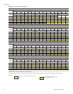
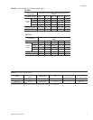
TABLE 7 - BLOWER MOTOR AND DRIVE DATA
*Allmotorsare1450RPMandhavea56frame,inherentprotectionandpermanentlylubricatedballbearingsThemotorshaveasolidbaseanda1.15serv
-
ice factor. All 3-phase motors are wired for 380/415V power supply.
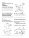
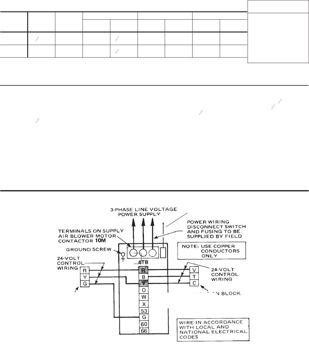
CONTROL WIRING
Route the low voltage control wiring through the
7
8
" (22.2mm)
hole (with bushing) in the units rear panel. Add
1
2
" (25mm) con
-
duit fitting to the
7
8
" (22.2mm) hole in the unit control box, route
control wiring through thisopening and connectthem to the ter
-
minals on block 4TB.
Refer to Table 6 to size the disconnect switch, the power wiring
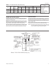
and the fuses. Refer to Figure 10 for typical field wiring.
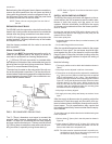
NOTE: Three phase motor rotation may be incorrect when the
unit is first started up. Reverse phase (leads L1 and
L2) at contactor to obtain the correct rotation.
FIG. 10 - TYPICAL FIELD WIRING (Cooling only)
TERMINALSONBLOCK3TBOF
THE BLOWER UNIT
TERMINALS ON
1-STAGE COOLING
THERMOSTAT
2TH0870124
LUG ON NEUTRAL TERMI-
NAL BLOCK
4 - WIRE