


REFRIGERANT MAINS
Many service problems can be avoided by taking adequate pre-
cautions to provide an internally clean and dry system, and by us-
ing procedures and materials that conform with established
standards.
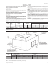
Hard drawn copper tubing should be used where no apprecia
-
ble amount of bending around pipes or other obstructions in
necessary. Use long radius ells wherever possible. If soft cop
-
per is used, care should be taken to avoid sharp bends which
may cause a restriction.
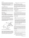
Pack fiber glass insulation and a sealing material such as Per
-
magum around refrigerant lines where they penetrate a wall to
reduce vibration and to retain some flexibility.
Support all refrigerant lines at minimum intervals (8 ft./2.4m)
with suitable hangers, brackets or clamps.
Braze all copper to copper joints witH Sil-Fos 5 or equivalent
brazing material. Do not use soft solder.
Never braze or solder liquid and suction lines together. The
complete suction line should be insulated with no less the
1
2
"
(12mm) ARMAFLEX or equivalent. If the liquid line is installed
in warm space, it must be insulated.
If it is desirable to tape or wire the liquid and suction lines to
-
gether for support purposes, they must be completely insulated
from each other.
INSTALLING REFRIGERANT MAINS
The units are evacuated and dehydrated at the factory and
shipped with a holding charge (1 lb./2.2kg) of Refrigerant-22.
The suction and liquid connections are sealed with copper
disks.
WARNING: Provisions for recovering refrigerant releases
must be available during all phases of installation,
leak testing and charging. Do NOT release refrig-
erant into theatmosphere. ASchradervalve ispro-
vided for refrigerant recovery.
If the unit has already lost its holding charge, it should be leak
tested and the necessary repairs should be made. If the unit
has maintained its holding charge, you can assume that it has
no leaks and proceed with the installation.
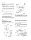
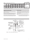
Make sure therefrigerant inthe lineshas beenrecovered, then
drill a small holethrough the discs to prevent any internal pres
-
sure from blowing them off and to allow the flow of dry nitrogen
through the connections when unbrazing the closures.
NOTE: To minimize the possibility of system failure due to dirt
and moisture, a filter-drier must be installed in each
liquid line as close to the evaporator as possible.
Filter-driersare notsupplied with the evaporator blow
-
ers. They are supplied with the matching condensing
sections.
The temperature required to make or break a brazed
joint is sufficiently high to cause oxidation of the copper
unless an inert atmosphere is provide.
CAUTION: Dry nitrogen should flow through a brazed joint at
all times when heat is being applied and until the
joint has cooled.
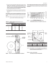
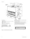
The liquid, suction and drain connections inside the unit
must be piped to the outside. Refer to Unit Dimensions
for locations and dimensions of these connection.
Unitary Products Group 5
550.39-N4YI
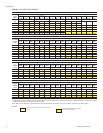
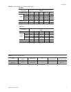
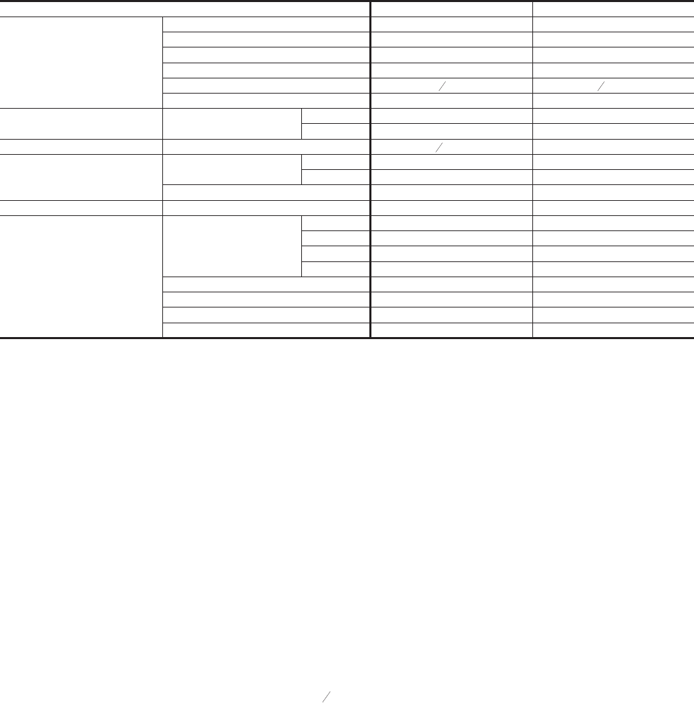
Model KEU090 KEU120
Evaporator Coil
Rows Deep 3 3
Rows High 27 32
Finned Length (in./mm) 46 / 1168 46 / 1168
Fin/Inch 13 13
Tube O.D. (in./mm)
3
8
/ 9.5
3
8
/ 9.5
Face Area (Ft
.2
/m
2
) 8.6 / 0.80 10.2 / 0.95
Centrifugal Blower Wheel Dia. x Width
inches 15 x15 15 x 15
mm 381 x 381 381 x 381
Blower Motor* Nominal Rating (HP/kW) 1
1
2
/ 1.12 2 / 1.5
Filters
(4 Req'd)
Size
inches 16 x 25 x 1 16 x 25 x 1
mm 406 x 635 x 25 406 x 635 x 25
Face Area (Ft.
2
/m
2
) 11.1 / 1.03 11.1 / 1.03
Weight (Lbs,/kg) Operating 325 / 147 330 / 150
Accessory Weights(Lbs/kg)
Electric Heaters
10 kW 63 / 28.6 63 / 28.6
16kW 66 / 30 66 / 30
26kW 71/32 71/32
36 kW 74 / 33.6 74 / 33.6
Supply Air Plenum 102 / 46 102 / 46
Base 60 / 27 60 / 27
Return Air Grille 15 / 6.8 15 / 6.8
Hot Water Coil 105 / 48 117 / 53
*Allofthese1450RPMmotorshaveasolidbase,a56frame,inherentprotectionandpermanentlylubricatedballbearings.RefertoTable7foradditionalmotoranddrive
data.
NOTE: Refer to the appropriate condensing unit installation instruction for charging data.
Table 2 - PHYSICAL DATA