


036-21300-002-A-0905
Unitary Products Group 19
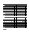
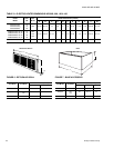
Plenum
Model
Unit
Model
Plenum Dimensions (inches)
ABCDEFGHKL
1SP0450 060 36 25-1/2 34-2/8 31-3/4 15-3/4 7-5/8 7/8 2-1/8 11-1/4 2
1SP0451
090
120
52-1/8 28-1/4 27-1/2 49-3/8 17-7/8 8-3/4 7/8 1-1/8 15-1/4 1-3/4
1SP0452 180 60-3/4 31 27 55-3/4 19-7/8 6-1/8 1- 2-1/2 19-1/2 1-3/4
(
*
)
+
'
$
+
%
/
.
&
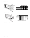
63
6+,33('.12&.(''2:1
)25),(/'$66(0%/<
6833/<$,53/(180
.12&.287)2532:(5:,5,1*
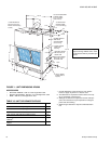
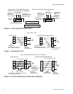
WITH ELECTRIC HEAT - Remove this 2-1/2” knockout from the
rear panel of the plenum. Route the power wiring conduit through
this opening and connect it to the field-supplied fitting on the elec-
tric heat accessory. Connect the power wiring to the fuse block in
the heater control box.
Install the control wiring per basic unit Installation Manual.
DO NOT route any field control wiring through the plenum.
WITHOUT ELECTRIC HEAT - Install the power and the control wiring
per basic unit Installation Manual. DO NOT route any wiring through
the plenum and DO NOT remove this knockout.
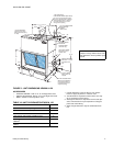
Electric Heaters are NOT CSA approved for installation
within a supply air plenum.
WITH ELECTRIC HEAT - Remove this 2-1/2” knockout and one of the 7/8”
knockouts from the rear panel of the plenum. Remove the 1-23/32” knockout
and one of the 7/8” knockouts from the top panel of the basic unit. Install a 1/
2” squeeze connector in both of the 7/8” openings.
Route the power wiring conduit through the 2-1/2” opening and connect it
to the field-supplied fitting on the electric heat accessory. Connect the
power wiring to the fuse block in the heater control box.
Route the control wires through the 7/8” openings and connect them to
the terminals on block TB1. Secure them with the 1/2” squeeze connec-
tors.
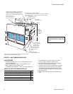
Electric Heaters are NOT CSA approved for installation
within a supply air plenum.
WITHOUT ELECTRIC HEAT - Remove both 7/8” knockouts from the rear
panel of the plenum and both 7/8” knockouts from the top panel of the
basic unit. Install a 1/2” squeeze connector in one of the plenum open-
ings and both of the unit openings. Install a 1/2” conduit fitting in the other
opening of the plenum.
Connect the power wiring conduit to the fitting on the plenum. Route the
power wiring through the conduit, one of the squeeze connectors on the
unit, and the field-supplied squeeze connector on the blower motor contac-
tor box. Connect the power wiring to the blower motor contactor.
Route the control wires through the remaining plenum and unit open-
ings and connect them to the terminals on block TB1. Secure them
with the 1/2” squeeze connectors.
.
63
.12&.2876)2532:(5&21752/:,5,1*
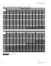
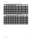
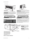
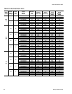
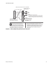
FIGURE 5 - ACCESSORY DIMENSIONS
+($7(5
(/(0(17
&+$0%(5
$
&
'
/
(
)
0
*
+
.
%
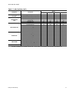
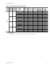
$&&(6623(1,1*)2532:(56833/<:,5,1*
:,5,1*+$51(66/2&$7,21
7KLVRSHQLQJLQWKHERWWRPRIWKHKHDWHU
FRQWUROER[LVXVHGIRUWKHZLULQJKDUQHVV
WKDWFRQQHFWVWKHKHDWHUDFFHVVRU\WRWKH
EDVLFXQLW,WLVSURYLGHGZLWKDVTXHH]H
FRQQHFWRUIRUVHFXULQJWKHZLULQJKDUQHVV
DQGLWVORFDWLRQFRUUHVSRQGVWRWKHORFD
WLRQRIWKHNQRFNRXWLQWKHWRS
SDQHORIWKHEDVLFXQLW
&21752/%2;
$&&(663$1(/
.:7+58.:$GGDFRQGXLWILWWLQJ
WRWKHKROHIRUZLUHVL]HVXSWKURXJK
$:*5HPRYHWKHNQRFNRXWULQJDQGDGGD
FRQGXLWILWWLQJWRWKHKROHIRU
ZLUHVL]HVXSWKURXJK$:*
.:7+58.:$GGDFRQGXLWILWWLQJ
WRWKHKROHIRUZLUHVL]HVXSWKURXJK
$:*5HPRYHWKHNQRFNRXWULQJDQGDGGD
FRQGXLWILWWLQJWRWKHKROHIRUZLUHVL]HV
XSWKURXJK$:*