


036-21300-002-A-0905
14 Unitary Products Group
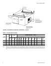
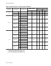
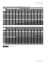
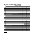
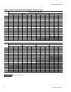
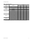
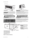
TABLE 15: SUPPLY AIR PLENUM PERFORMANCE DATA
Model CFM
Face
Velocity
(FPM)
Angle of Deflection
Vertical
Louvers
1
(Plan
View)
Horizontal
Louvers
2
(Elevation
View)
Vertical
Louvers
(Plan
View)
Horizontal
Louvers
(Elevation
View)
Vertical
Louvers
(Plan
View)
Horizontal
Louvers
(Elevation
View)
Throw
(Feet)
Spread
(Feet)
3
Throw
(Feet)
Spread
(Feet)
Throw
(Feet)
Spread
(Feet)
Min. Max. Min. Max
Drop (Feet)
4
Min. Max Min. Max Drop (Feet) Min. Max. Min. Max. Drop (Feet)
060
1600 630 38 59 13 20 15 8 27 43 12 19 14 7 21 32 33 48 8 4
1800 710 43 67 14 22 16 8 30 48 14 22 14 7 23 37 35 56 8 4
2000 790 48 74 16 25 16 9 34 53 15 24 14 8 25 40 38 60 9 5
2200 870 52 81 17 27 16 9 37 58 17 26 15 8 29 44 44 66 9 5
2400 940 57 89 19 30 17 9 41 64 18 29 15 8 30 48 45 72 9 5
090
2400 615 47 74 20 29 19 9 34 53 23 33 17 8 26 39 45 65 9 5
2700 690 53 83 22 32 20 10 39 59 25 36 18 9 29 45 48 71 10 5
3000 770 59 92 24 35 21 10 42 66 27 40 19 9 32 50 52 78 10 5
3300 845 65 101 26 38 21 10 46 73 29 44 19 9 35 55 56 85 10 5
3600 920 71 110 28 41 22 11 50 79 32 47 20 10 38 60 60 91 11 6
120
3200 820 63 98 25 37 21 10 45 70 29 43 19 9 34 53 54 82 10 5
3600 920 71 110 28 41 22 11 50 79 32 47 20 10 38 60 60 91 11 6
4000 1025 78 123 30 45 22 11 56 88 35 52 20 10 42 66 67 102 11 6
4400 1130 86 135 33 49 23 12 62 97 38 57 21 11 47 73 76 115 12 6
4800 1230 94 147 35 53 23 12 68 106 41 62 21 11 51 80 85 127 12 6
180
4800 880 84 132 32 48 23 12 61 95 38 56 21 11 46 72 73 112 12 6
5400 1000 95 149 36 54 24 12 68 107 42 63 22 11 52 81 81 124 12 6
6000 1110 106 165 39 59 25 13 76 119 46 69 23 12 57 89 90 138 13 7
6600 1220 116 182 43 65 26 13 84 131 50 76 23 12 63 98 99 152 13 7
7200 1330 126 199 46 70 27 14 92 143 55 83 24 12 68 107 109 166 14 7
1. Adjusting the vertical louvers will vary the throw, the spread and the drop.
2. Adjusting the horizontal louvers will only vary the drop.
3. The velocity of the air will be 125 ft./min. at the minimum distance and 80 ft./min. at the maximum distance.
4. The velocity of the conditioned air at the bottom of the drop will be 50 ft./min. Drafts will occur if the drop extends into the occupied
level of the conditioned space.
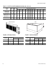
0 °
S P R E A D
2 2 - 1 / 2 °
S P R E A D
4 5 °
S P R E A D
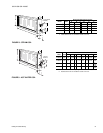
0 °
S P R E A D
18
˚
0 °
S P R E A D
18˚
0 °
S P R E A D
18
˚
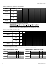
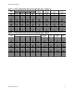
TABLE 16: BLOWER MOTOR AND DRIVE DATA
MODEL
BLOWER
RANGE
(RPM)
MOTOR ADJUSTABLE MOTOR PULLEY FIXED BLOWER PULLEY BELT (NOTCHED)
HP FRAME
DESIG-
NATION
OUTSIDE
DIA.
(IN.)
PITCH
DIA.
(IN.)
BORE
(IN.)
DESIG-
NATION
OUTSIDE
DIA.
(IN.)
PITCH
DIA.
(IN.)
BORE
(IN.)
DESIG-
NATION
PITCH
LENGTH
(IN.)
QTY.
060 810/1110 3/4 56 1VL44 3.1-4.1 2.8-3.8 5/8 AL64 6.2 5.8 3/4 A32 33.3 1
090 655/880 1-1/2 56 1VL44 2.1-4.1 2.8-3.8 7/8 AK79 7.9 7.5 1 A36 37.3 1
120 700/950 2 56 1VL44 3.1-4.1 2.8-3.8 7/8 BK80 7.4 7.0 1 A36 37.3 1
180 625/810 3 56 1VM50 3.7-4.7 3.4-4.4 7/8 BK105 9.9 9.5 1 A57 58.3 1