


268890-UIM-B-0607
8 Unitary Products Group
Downflow Filters
Downflow furnaces typically are installed with the filters located above
the furnace, extending into the return air plenum or duct. Any branch
duct (rectangular or round duct) attached to the plenum must attach to
the vertical plenum above the filter height.
Filters(s) may be located in the duct system external to the furnace
using an external duct filter box attached to the furnace plenum or at the
end of the duct in a return filter grille(s). The use of straps and / or sup-
ports is required to support the weight of the external filter box.
If the accessory electronic air cleaner is installed, be sure the air
cleaner is designed to accommodate the furnace CFM (cm/m) and the
air cleaner is installed so it does not obstruct the return airflow. Consid-
eration should be given when locating the air cleaner for maintenance
and temperatures should the indoor fan motor fail to operate. The use
of straps and / or supports is required to support the weight of the elec-
tronic air cleaner. It is recommended that the air cleaner not be located
within 12 inches (30.5 cm) from the top of the return air opening on the
furnace. Refer to the instructions supplied with the electronic air
cleaner.
If pleated media air filters or any filter that has a large pressure drop is
installed in the return air duct system be sure that the pressure drop
caused by the air filter will not prevent the furnace from operating within
the rise range specified on the rating plate. If the furnace does not oper-
ate within the specified rise range then a larger air filter or an air filter
that has a lower pressure drop must be installed.
IMPORTANT: For easier filter access in a downflow configuration, a
removable access panel is recommended in the vertical run of the
return air plenum immediately above the furnace.
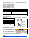
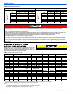
IMPORTANT: Air velocity through throwaway type filters must not
exceed 300 feet per minute (91 m/min). All velocities over this require
the use of high velocity filters. Refer to Table 19.
HORIZONTAL APPLICATION
Horizontal Filters
All filters and mounting provision must be field supplied. Filters(s) may
be located in the duct system external to the furnace or in a return filter
grille(s). Filters(s) may be located in the duct system using an external
duct filter box attached to the furnace plenum. Any branch duct (rectan-
gular or round duct) attached to the plenum must attach to the vertical
plenum above the filter height. The use of straps and / or supports is
required to support the weight of the external filter box.
An accessory filter rack is available.
ATTIC INSTALLATION
This appliance is design certified for line contact when the furnace is
installed in the horizontal left or right position. The line contact is only
permissible between lines are formed by the intersection of the top and
two sides of the furnace and the building joists, studs or framing. This
line may be in contact with combustible material.
IMPORTANT: In either a horizontal left or right installation, a minimum
of 8" (20.3 cm) clearance is required beneath the furnace to allow for
the installation of the condensate trap and drain pipe. Refer to "CON-
DENSATE PIPING" section of this manual for more information.
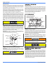
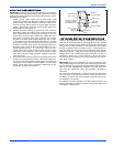
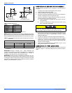
SUSPENDED FURNACE / CRAWL SPACE
INSTALLATION
The furnace can be hung from floor hoists or installed on suitable blocks
or pad. Blocks or pad installations shall provide adequate height to
ensure the unit will not be subject to water damage. Units may also be
suspended from rafters or floor joists using rods, pipe angle supports or
straps. Angle supports should be placed at the supply air end and near
the blower deck. Do not support at return air end of unit. All four sus-
pension points must be level to ensure quite furnace operation. When
suspending the furnace use a secure a platform constructed of plywood
or other building material secured to the floor joists. Refer to Figure 6
for typical crawl space installation.
All loose accessories shipped with the furnace must be removed
from the blower compartment, prior to installation.
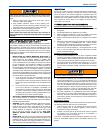
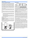
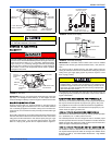
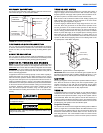
FIGURE 4: Return Filter Grill and Return Duct Installation
All installations must have a filter installed.
COMBUSTION
AIR
VENT
PIPE
ELECTRICAL
SUPPLY
GAS SUPPLY
(EITHER SIDE)
CLOSET
RETURN
AIR
AIR
FILTERS
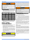
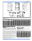
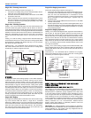
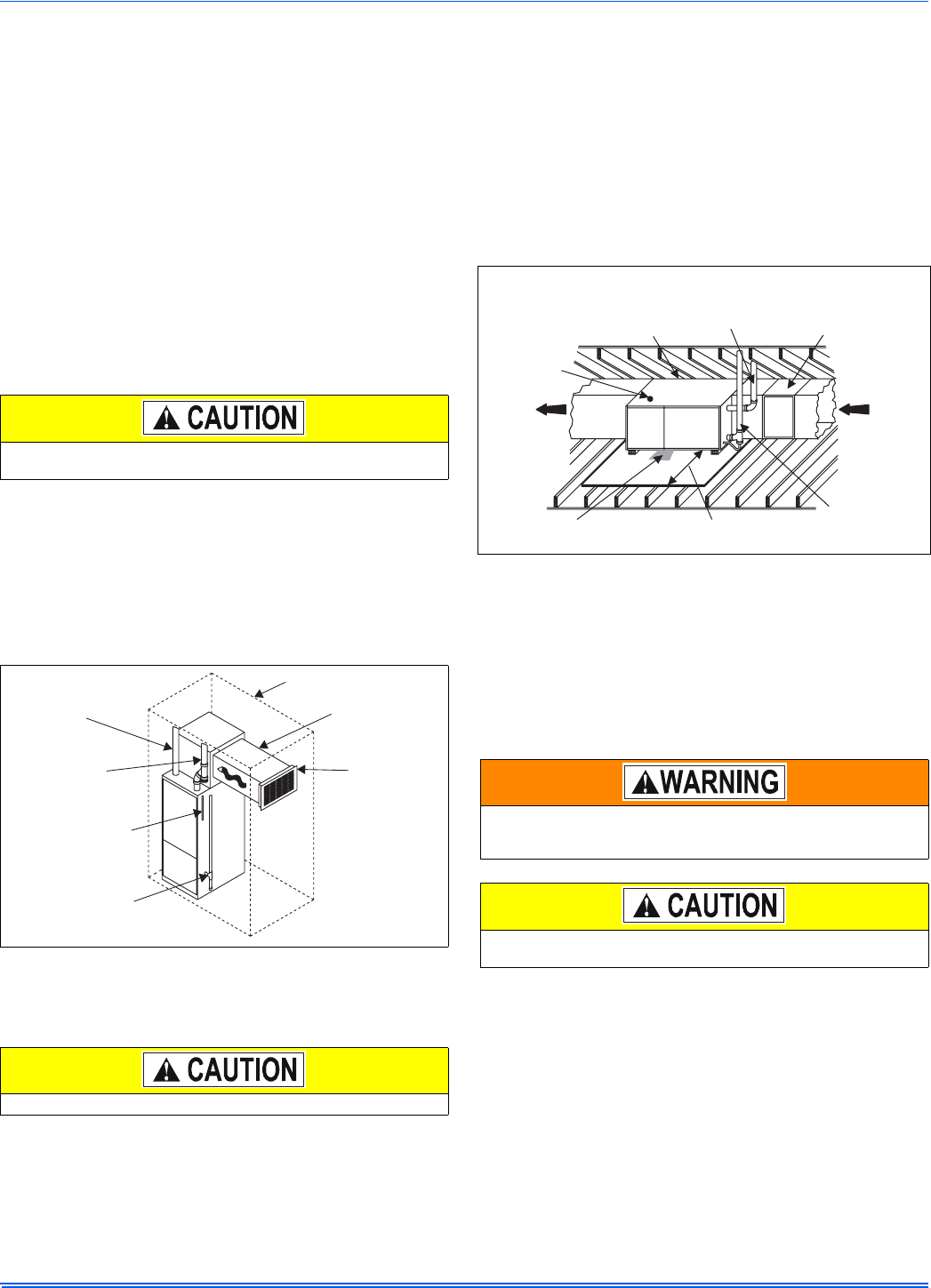
FIGURE 5: Typical Attic Installation
When a furnace is installed in an attic or other insulated space,
keep all insulating materials at least 12 inches (30.5 cm) away from
furnace and burner combustion air openings.
If this furnace is installed over a finished space, a condensate
safety pan must be installed.
LINE CONTACT ONLY PERMISSIBLE
BETWEEN LINES FORMED BY THE
INTERSECTION OF FURNACE TOP
AND TWO SIDES AND BUILDING
JOISTS, STUDS OR FRAMING
FILTER RACK
COMBUSTION
AIR
GAS
PIPING
VENT PIPE
(maintain required
clearances to
combustible)
RETURN
AIR
SUPPLY
AIR
12” CLEARANCE
FOR SERVICE
30” MIN.
WORK AREA