


268890-UIM-B-0607
32 Unitary Products Group
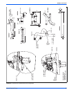
There is an accessory kit (1PK0601) available from Source 1, which
has the following items:
• 1 - 12” (30 cm) length x 1/8” (0.3 cm) diameter tubing
• 2 – pieces of 4” (10 cm) length x 1/8” (0.3 cm) diameter tubing
• 1 - 5/16” (0.8 cm) tee
• 1 – 5/16” (0.8 cm) x 1/8” (3.175 mm) reducing coupling
• 1 – 1/8” (0.3 cm) adapter
There is a accessory kit (1PK0602) available from Source 1, which has
the following items:
• 12” (30 cm) length x 1/8” (0.3 cm) diameter tubing
• 2 – pieces of 4” (10 cm) length x 1/8” (0.3 cm) diameter tubing
• 1 - 5/16” (0.8 cm) tee
• 1 – 5/16” (0.8 cm) x 1/8” (0.3 cm) reducing coupling
• 1 – 1/8” (0.3 cm) adapter
• 1 - Dwyer – Manometer
These items are required in order to properly perform the required star-
tup procedure.
IGNITION SYSTEM SEQUENCE
1. Turn the gas supply ON at external valve and main gas valve.
2. Set the thermostat above room temperature to call for heat.
3. System start-up will occur as follows:
a. The induced draft blower motor will start and come up to
speed. Shortly after inducer start-up, the hot surface igniter
will glow for about 17 seconds.
b. After this warm up, the ignition module will energize (open)
the main gas valve.
c. After flame is established, the supply air blower will start in
about 30 seconds.
IMPORTANT: Burner ignition may not be satisfactory on first startup
due to residual air in the gas line or until gas manifold pressure is
adjusted. The ignition control will make 3 attempts to light before lock-
ing out.
With furnace in operation, check all of the pipe joints, gas valve connec-
tions and manual valve connections for leakage using an approved gas
detector, a non-corrosive leak detection fluid, or other leak detection
methods. Take appropriate steps to stop any leak. If a leak persists,
replace the component.
The furnace and its equipment shutoff valve must be disconnected from
the gas supply piping system during any pressure testing of that system
at test pressures in excess of 1/2 PSI (3.45 kPa).
The furnace must be isolated from the gas supply piping system by
closing the equipment shutoff valve during any pressure testing of the
gas supply piping system.
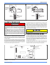
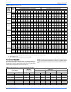
CALCULATING THE FURNACE INPUT
(NATURAL GAS)
NOTE: Burner orifices are sized to provide proper input rate using natu-
ral gas with a heating value of 1030 BTU/Ft
3
(38.4 MJ/m
3
). If the heat-
ing value of your gas is significantly different, it may be necessary to
replace the orifices.
NOTE: Front door of burner box must be secured when checking gas
input.
1. Turn off all other gas appliances connected to the gas meter.
2. At the gas meter, measure the time (with a stop watch) it takes to
use 2 cubic ft. (0.0566 m
3
.) of gas.
3. Calculate the furnace input by using one of the following equa-
tions.
FIRE OR EXPLOSION HAZARD
Failure to follow the safety warnings exactly could result in serious
injury, death or property damage.
Never test for gas leaks with an open flame. Use a commercially
available soap solution made specifically for the detection of leaks
to check all connections. A fire or explosion may result causing
property damage, personal injury or loss of life.