


268890-UIM-B-0607
16 Unitary Products Group
Dimensions are those required in Standard ASTM D-3311.
NOTE: Sidewall vent terminal may be used for sidewall vent termina-
tions. Refer to part list in the back of the USERS INFORMATION AND
SERVICE AND MAINTENANCE MANUAL for the terminal part number.
*. Vent pipe size must be increased to 3” diameter after connection to furnace
on this model.
IMPORTANT: Accessory concentric vent / intake termination kits
1CT0302 and 1CT0303 are available and approved for use with these
furnaces. Horizontal sidewall vent terminations kits 1HT0901 &
1HT0902 are also approved for use with these furnaces.
IMPORTANT: Furnace vent pipe connections are sized for 2” (5.1 cm).
pipe. Any pipe size change must be made outside the furnace casing in
a vertical pipe section to allow proper drainage of condensate. An offset
using two 45º (degree) elbows will be required for plenum clearance
when the vent is increased to 3” (7.6 cm).
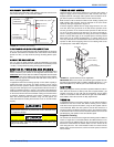
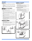
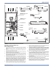
COMBUSTION AIR AND VENT PIPING ASSEMBLY
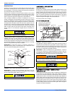
The final assembly procedure for the combustion air and vent piping is
as follows:
1. Cut piping to the proper length beginning at the furnace.
2. Deburr the piping inside and outside.
3. Chamfer (bevel) the outer edges of the piping.
4. Dry-fit the vent piping assembly from the furnace to the outside ter-
mination checking for proper fit support and slope.
5. Dry-fit the combustion air piping assembly checking for proper fit,
support and slope on the following systems:
A. Sealed combustion air systems from the furnace to the out-
side termination.
B. Ventilated combustion air systems from the furnace to the
attic or crawl space termination.
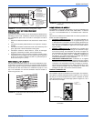
6. Disassemble the combustion air and vent piping, apply cement
primer and the cement per the manufactures instructions. Primer
and cement must conform to ASTM D2564 for PVC, or ASTM
D2235 for ABS piping.
7. All joints must provide a permanent airtight and watertight seal.
8. Support the combustion air and vent piping such that it is angled a
minimum of 1/4” per foot (0.635 cm/m) so that condensate will flow
back towards the furnace. Piping should be supported with pipe
hangers to prevent sagging.
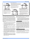
9. Seal around the openings where the combustion air and / or vent
piping pass through the roof or sidewalls.
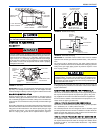
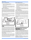
COMBUSTION AIR / VENT CLEARANCES
IMPORTANT: The vent must be installed with the minimum clearances
as shown in Figure 17, and must comply with local codes and require-
ments.
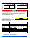
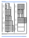
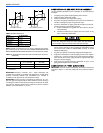
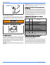
FIGURE 16:
Dimensions
TABLE 10: Elbow
Dimensions
Elbow "A" Dimension
2" Standard 2-5/16"
3" Standard 3-1/16"
2" Sweep 3-1/4"
3" Sweep 4-1/16"
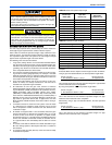
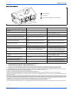
TABLE 11:
Combustion Air Intake and Vent Connection Size at Furnace
(All Models)
FURNACE VENT CONNECTION SIZES
Furnace Input
40 - 100 MBH
(17.5 - 29.3 kW)
120 MBH
(35.2 kW)
Intake Pipe Size 2” (5.1 cm) 3” (7.6 cm)
Vent Pipe Size 2” (5.1 cm) 2” (5.1 cm)
A
A
A
A
STANDARD ELBOW
LONG (SWEEP) ELBOW
Solvent cements are flammable and must be used in well-ventilated
areas only. Keep them away from heat, sparks and open flames.
Do not breathe vapors and avoid contact with skin and eyes.