


272442-UUM-B-1211
Unitary Products Group 7
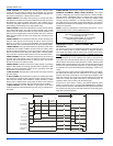
If the flame is not detected within 7 seconds of the gas valve opening,
the gas valve is shut off and a retry operation begins. If the flame is lost
for 2 seconds during the 10-second stabilization period, the gas valve is
shut off and a retry operation begins. During a retry operation, the vent
motor starts a 15 second inter-purge and the igniter warm-up time is
extended to 27 seconds. If the flame is established for more than 10
seconds after ignition during a retry, the control will clear the ignition
attempt (retry) counter. If three retries occur during a call for heat, the
furnace will shut down for one hour. If at the end of the one hour shut
down there is a call for heat, the furnace will initiate a normal start cycle.
If the problem has not been corrected the furnace will again lockout
after three retries.
A momentary loss of gas supply, flame blowout, or a faulty flame probe
circuit will result in a disruption in the flame and be sensed within 1.0
seconds. The gas valve will de-energize and the control will begin a
recycle operation. A normal ignition sequence will begin after a 15 sec-
ond inter-purge. If during the five recycles the gas supply does not
return, or the fault condition is not corrected the ignition control will lock-
out for 60 minutes.
During burner operation, a momentary loss of power for 50 milliseconds
or longer will de-energize the gas valve. When the power is restored,
the gas valve will remain de-energized and the ignition sequence will
immediately restart.
Hot Surface Ignition System
TROUBLESHOOTING
The following visual checks should be made before troubleshooting:
1. Check to see that the power to the furnace and the ignition control
module is ON.
2. The manual shut-off valves in the gas line to the furnace must be
open.
3. Make sure all wiring connections are secure.
4. Review the sequence of operation. Start the system by setting the
thermostat above the room temperature. Observe the system’s
response. Then use the troubleshooting section in this manual to
check the system’s operation.
FURNACE CONTROL DIAGNOSTICS
The furnace has built-in, self-diagnostic capability. If a system problem
occurs, a blinking LED shows a fault code. The LED can flash red,
green or amber to indicate various conditions. It is located behind a
clear view port in the blower compartment door.
The control continuously monitors its own operation and the operation
of the system. If a failure occurs, the LED will indicate the failure code. If
the failure is internal to the control, the light will stay on continuously. In
this case, the entire control should be replaced, as the control is not
field repairable.
Flash sequence codes 1 through 11 are as follows: LED will turn “on”
for 1/4 second and “off” for 1/4 second. This pattern will be repeated the
number of times equal to the code. For example, six “on” flashes equals
a number 6 fault code. All flash code sequences are broken by a 2 sec-
ond “off” period.
SLOW GREEN FLASH: Normal operation.
SLOW AMBER FLASH: Normal operation with call for heat.
RAPID RED FLASH: Twinning error, incorrect 24V phasing. Check
twinning wiring.
RAPID AMBER FLASH: Flame sense current is below 1.5 microamps.
Check and clean flame sensor. Check for proper gas flow. Verify that
current is greater than 1.5 microamps at flame current test pad.
4 AMBER FLASHES: The control board is recieving a “Y” signal from
the thermostat without a “G” signal, indicating improper thermostat wir-
ing.
1 RED FLASH: This indicates that flame was sensed when there was
not a call for heat. With this fault code the control will turn on both the
inducer motor and supply air blower. A gas valve that leaks through or
is slow closing would typically cause this fault.
2 RED FLASHES: This indicates that the normally open pressure
switch contacts are stuck in the closed position. The control confirms
these contacts are open at the beginning of each heat cycle. This would
indicate a faulty pressure switch or miswiring.
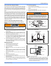
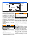
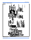
FIGURE 10: Furnace Control Board
PARK
PARK
HI COOL
HEAT
EAC-H
L1
XFMR
NEUTRALS
HUM
TWIN
60
90
120
180
BLOWER
OFF
DELAY
Y/Y2
W
R
G
C
FAN OFF
ADJUSTMENT
JUMPER
RED-LOW
YELLOW-MED. LOW
BLACK-HI
BLUE-MED. HI
HOT SURFACE IGNITION SYSTEM
Do not attempt to light this furnace by hand (with a
match or any other means). There may be a potential
shock hazard from the components of the hot surface
ignition system. The furnace can only be lit automatically
by its hot surface ignition system.
Never bypass pressure switch to allow furnace opera-
tion. To do so will allow furnace to operate under poten-
tially hazardous conditions.
Do not try to repair controls. Replace defective controls
with UPG Source 1 Parts.
Never adjust pressure switch to allow furnace operation.