


272442-UUM-B-1211
4 Unitary Products Group
FURNACE USER MAINTENANCE
Every time the filters are changed the following items should be visually
inspected:
• Check combustion air and vent pipe for blockage or leakage.
• Check all components to be sure they are in good condition and
that there are no obvious signs of deterioration.
• Check the drain lines to make sure there are no cracks or leaks.
• Check for dirt or lint on any surfaces or on components. Do not try
to clean any of the surfaces or components. Cleaning of the fur-
nace and its components must be done by a qualified service pro-
fessional.
If, during the inspection of your furnace, you find any of the following
conditions:
• Excessive amounts of dust and lint on components.
• Damaged or deteriorated components or surfaces.
• Leaks or blockage in the vent pipe passages.
• Water on any surface inside or outside of the furnace.
Do not operate the furnace, call a certified dealer / servicing contractor
to check and / or clean your furnace, or for more information if you have
questions about the operation of your furnace.
If all components appear to be in good operating condition, replace the
front panels. Turn ON the gas and electrical power supplies to the fur-
nace, and set thermostat to the desired temperature.
Air Filters
Dirty filters greatly restrict the flow of air and may cause damage to the
moving parts of the furnace. If the filters become clogged the heat
exchangers and blower motor could overheat resulting in a potentially
dangerous situation. The filters should be checked every 3 months. On
new construction, check the filters every week for the first four weeks
and every three weeks after that, especially if the indoor fan is running
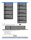
continuously. When replacing the filter(s) you must use filters that are
the same size as those recommended in Table 1. Use the following pro-
cedure to determine the filter size. Never operate your furnace without a
suitable air filter.
1. Determine whether you have a bottom or side return air duct using
the following method.
a. If the return air filter is on the left or right side of the furnace it
is a side return
b. If the air filter is on the bottom of the furnace then you have a
bottom return.
c. If the air filters are on the bottom and the side of the furnace
then you have a bottom and side return. You must replace
both air filters. Table 1 will indicate 2 filters by using brackets
with the number two (2).
d. If the air filters are on both sides of the furnace then you have
a two sided return. You must replace both air filters. Table 1
will indicate 2 filters by using brackets with the number two
(2).
2. After you determine the cabinet size and what return configuration
you have, look up the recommended filter size from Table 1.
Removing the Air Filters
Externally Bottom Mounted Air Filters
This furnace has the filter(s) mounted externally to the cabinet on either
both sides of the cabinet, one side and the bottom of the cabinet, or the
bottom of the cabinet only. DO NOT place the air filter(s) on the inside
of the blower compartment on this furnace. The air filter(s) must be
place in the externally mounted air filter hardware. Follow the instruc-
tions below to remove and replace the air filter(s).
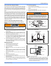
1. Before removing the air filters follow the instructions “To turn off
the Appliance” on page 3.
2. Remove the cover on the front of the filter box by removing the
retaining screw or knob that secures the cover to the box. The
external filter box will be located on the bottom of the furnace cab-
inet. Refer to Figure 7 for upflow filter box locations or Figure 8 for
horizontal filter box locations.
3. Use your fingers to grab the outside edge of the filter and remove
the filter(s) from the filter box.
4. If the filter(s) are permanent cleanable filter(s) follow the instruc-
tions on how to clean your filter or you may replace the throwaway
filter with permanent cleanable filter(s) at this time. Refer to Table
1 for the recommended air filter size.
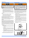
5. Install the filter(s). The filter(s) should fit in the entire filter track. If
the filter does not fit inside the entire filter track then the filter you
have is the wrong size. Refer to Table 1 for the recommended filter
size.
6. Reinstall the filter box access cover.
7. Follow the Operating Instructions on page 3 to place the furnace
back in service.
Before proceeding, be sure the area is well ventilated. Turn
the thermostat OFF. If the blower is running, wait until it
stops automatically. Turn OFF the gas and electrical power
supplies to the furnace. Check all metal parts and surfaces
to be sure they have cooled to room temperature before
you begin.
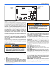
Turn off ALL electrical power to the furnace when conduct-
ing any service or inspection procedure. Furnace may
have isolated electrical supplies - one providing power to
the Circulating Blower (230V or 115V) and another supply-
ing the control circuit (115V), which controls the Circulat-
ing Blower. The spring loaded safety cutoff switch,
mounted to the blower deck DOES NOT interrupt all electri-
cal potential in the blower compartment when the blower
access panel is removed.
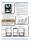
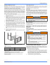
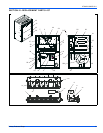
FIGURE 7: Bottom Return Filter Rack
FIGURE 8: Bottom Return Filter Rack in the Horizontal Position
A
B
FILTER
RACK
FURNACE
RETURN AIR
PLATFORM
RETURN
DUCT
SYSTEM