


272442-UUM-B-1211
6 Unitary Products Group
FURNACE CLEANING SECTION
NOTE: The cleaning operations listed below must be performed only by
a qualified service agency.
Burner Removal/Cleaning
The main burners should be checked periodically for dirt accumulation.
If cleaning is required, follow this procedure:
1. Turn off the electrical power to the unit.
2. Turn off the gas supply at the external manual shut-off valve and
loosen the ground union joint.
3. Remove the upper access panel and remove the burner box cover.
4. Disconnect wires from flame sensor, rollout switch and HSI igniter.
Remove igniter carefully, as it is easily broken.
5. Remove the screws that hold the burner box assembly to the vest
panel and remove the assembly.
6. Remove burners from the burner assembly.
7. Burners may be cleaned by rinsing in hot water.
8. Reassemble the burners in the reverse order.
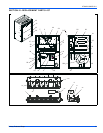
Cleaning the Heat Exchanger
Lower Heat Exchanger Access
1. Turn off the electrical power to the unit and turn off gas supply at
the shutoff valve.
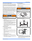
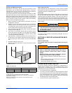
2. Remove the blower and burner compartment access doors. Dis-
connect the gas supply piping at the union to permit removal of the
entire burner and gas control assembly from the vestibule panel.
Use the wrench boss on the gas valve when removing or installing
this piping. See Figure 4.
3. Unplug the igniter from the wire harness. Disconnect sensor and
rollout switch wires located on top of the air shield. Identify and
note the location of all leads for ease of reinstallation. Also discon-
nect the wires at the side rollout switches (upflow only) and the gas
valve wires.
4. Remove the screws holding the burner assembly to the vestibule
panel and remove this assembly. Handle the assembly carefully
since it contains the igniter, which is fragile and easily broken. The
lower portion of the heat exchanger will now be exposed. To clean
the burner assembly, use a vacuum cleaner, or remove the burn-
ers as outlined in burner cleaning, and clean in hot water.
Upper Heat Exchanger Access
1. Perform steps 1-4 above.
2. Disconnect vent piping from the vent motor assembly at the top
panel on the furnace (upflow only). On downflow models, the vent
pipe is secured to the vent motor outlet with a screw. Remove this
screw before proceeding.
3. Unplug the vent motor wires and ground wire. Remove the pres-
sure switch tubing at the top on the vent motor housing.
NOTE: It is recommended that replacement gaskets be available
before removing vent motor.
1. Remove six mounting screws that hold the vent motor to the
restrictor plate. The surface is gasketed and the gasket can be
reused if it is carefully removed. It is necessary to remove this
assembly to gain access to the restrictor plate mounting holes.
The assembly may be vacuumed if cleaning is necessary. If any
vent assembly parts are damaged, replace with an entire new
assembly (except for gaskets).
2. Remove the perimeter screws attaching the restrictor plate assem-
bly to the vestibule panel. The surface is also gasketed. The
assembly, including the flue baffle plate (rear) may be vacuumed
or cleaned with hot water if necessary.
3. The upper portion of the heat exchanger is now accessible. With a
long flexible wire brush, clean inside each tube at both the top and
bottom. The brush must pass around the rear heat exchanger
tubes. Vacuum loose scale and dirt from each tube.
4. Clean - Replace all components in reverse order. Re-gasket all
surfaces which required a gasket. Reconnect all wiring. Reattach
vent pipe and gas supply lines before restoring service to furnace.
Restore electrical power, check gas supply piping for leaks, and
then verify furnace operation.
SEQUENCE OF OPERATION
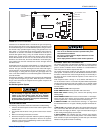
The following describes the sequence of operation of the furnace. Refer
to Figure 1 for component location.
Continuous Blower
Cooling/heating thermostats have a fan switch that has an ON and
AUTO position. In the ON position the thermostat circuit is completed
between terminals R and G. The motor will operate on the speed tap
wire that is connected to the cooling terminal on the control board.
Intermittent Blower
Cooling/heating thermostats have a fan switch that has an ON and
AUTO position. In the AUTO position the thermostat circuit is completed
between terminals R and G when there is a call for cooling and termi-
nals R and W when there is a call for heating. The integrated control will
energize the delay ON timer relay, which is a non-adjustable fan on
delay timer. The delay on timer relay will energize the indoor fan motor
relay after the delay ON time has expired. The indoor fan motor will be
turned off after the delay OFF time on the integrated control has
expired. The delay OFF time is adjustable by changing the jumper pin
setting on the integrated control. Refer to Figure 10 for the location of
the fan off adjustment jumper. The fan off setting is fixed at 60 seconds
for SEER enhancement.
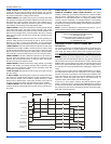
Heating Cycle
When the thermostat switch is set on HEAT and the fan is set on AUTO,
and there is a call for heat, a circuit is completed between terminals R
and W of the thermostat. When the proper amount of combustion air is
being provided, the pressure switch will close, the ignition control pro-
vides a 17-second warm-up period, the gas valve then opens, the gas
starts to flow, ignition occurs and the flame sensor begins its sensing
function. The blower motor will energize 30 seconds after the gas valve
opens, if a flame is detected. Normal furnace operation will continue
until the thermostat circuit between R and W is opened, which causes
the ignition system and gas valve to de-energize and the burner flames
to be extinguished. The vent motor will operate for 15 seconds and the
blower motor will operate for the amount of time set by the fan-off delay
jumper located on the control board. See Figure 10. The heating cycle
is complete, and ready for the start of the next heating cycle.
Label all wires prior to disconnection when servicing
controls. Wiring errors can cause improper and danger-
ous operation. Verify proper operation after servicing.