


271015-UUM-A-0407
8 Unitary Products Group
4 RED FLASHES: This indicates that a primary or auxiliary limit switch
has opened its normally closed contacts. With this fault code the control
will operate the supply air blower and inducer. This condition may be
caused by: dirty filter, improperly sized duct system, incorrect blower
speed setting, incorrect firing rate or faulty blower motor.
5 RED FLASHES: This fault is indicated if the normally closed contacts
in the rollout switch opens. The rollout control is manually reset. If it has
opened, check for proper combustion air, proper inducer operation, and
primary heat exchanger failure or burner problem. Be sure to reset the
switch after correcting the failure condition.
6 RED FLASHES: This indicates that after the unit was operating, the
pressure switch opened 4 times during the call for heat. If the main
blower is in a “Delay on” mode it will complete it, and any subsequent
delay off period. The furnace will lock out for one hour and then restart.
7 RED FLASHES: This fault code indicates that the flame could not be
established. This no-light condition occurred 3 times (2 retries) during
the call for heat before locking out. Low gas pressure, faulty gas valve,
faulty hot surface ignitor or burner problem may cause this. The furnace
will lock out for one hour and then restart.
8 RED FLASHES: This fault is indicated if the flame is lost 5 times (4
recycles) during the heating cycle. This could be caused by low gas
pressure or faulty gas valve. The furnace will lock out for one hour and
then restart.
9 RED FLASHES: Indicates reversed line voltage polarity or grounding
problem. Both heating and cooling operations will be affected. Check
polarity at furnace and branch. Check furnace grounding. Check that
flame probe is not shorted to chassis.
10 RED FLASHES: Gas valve energized with no call for heat. Check
gas valve and gas valve wiring.
11 RED FLASHES: This indicates that a primary or auxiliary limit switch
has opened its normally-closed contacts and has remained open for
more than five minutes. This condition is usually caused by a failed
blower motor or blower wheel.
12 RED FLASHES: This code indicates an open igniter circuit, which
could be caused by a disconnected or loose wire or by a cracked or bro-
ken igniter.
STEADY ON RED: Control failure. Replace control board.
60-MINUTE AUTOMATIC RESET FROM LOCKOUT: This control
includes a “watchdog” type circuit that will reset from a lockout condition
after 60 minutes. Operational faults 6,7,8 will be reset. This provides
protection to an unoccupied structure if a temporary condition exists
causing a furnace malfunction. An example would be a low incoming
gas supply pressure preventing unit operation. When the gas pressure
is restored, at some point the “watchdog” would restart the unit and pro-
vide heat for the house.
NOTE: If a flame is detected the control flashes the LED for 1/8 of a
second and then enters a flame stabilization period.
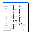
DIAGNOSTIC FAULT CODE STORAGE AND
RETRIEVAL
The control in this furnace is equipped with memory that will store up to
five error codes to allow a service technician to diagnose problems
more easily. This memory will be retained even if power to the furnace
is lost. This feature should only be used by a qualified service tech-
nician.
The control stores up to five separate error codes. If more than five
error codes have occurred since the last reset, only the five most recent
will be retained. The furnace control board has a button, labeled "LAST
ERROR" that is used to retrieve error codes. This function will only work
if there are no active thermostat signals. So any call for heating, cooling
or continuous fan must be terminated before attempting to retrieve error
codes.
To retrieve the error codes, push the LAST ERROR button. The LED on
the control will then flash the error codes that are in memory, starting
with the most recent. There will be a two-second pause between each
flash code. After the error codes have all been displayed, the LED will
resume the normal slow green flash after a five second pause. To
repeat the series of error codes, push the button again.
If there are no error codes in memory, the LED will flash two green
flashes. To clear the memory, push the LAST ERROR button and hold it
for more than five seconds. The LED will flash three green flashes when
the memory has been cleared, then will resume the normal slow green
flash after a five-second pause.
IGNITION CONTROL
Normal flame sense current is approximately
3.7 microamps DC (µa)
Low flame signal warning starts at 1.5 microamps.
Low flame signal control lockout point is
0.1 microamps DC (µa)