


271015-UUM-A-0407
Unitary Products Group 7
Continuous Blower Operation
The blower will run continuously whenever the wall thermostat fan
switch is in the "ON" position. The furnace blower will run at the speed
selected on the "FAN SPEED" jumpers on the main control board (HI
COOL, LO COOL, HI HEAT or LO HEAT). When the jumper is in the
"VS G" position, the blower will run at 50% of the high cool speed.
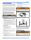
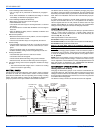
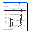
Delay Tap Selection
The set of jumper pins on the control board labelled "DELAY" are used
to set the delay profiles for the furnace. These can be chosen so as to
maximize the comfort and sound levels for various regions of the coun-
try.
Tap A is the default profile. It provides a 15-second ramp-up from zero
airflow to full capacity and a 15-second ramp-down from full capacity
back to zero airflow. Whenever there is a change in airflow mode, such
as from low heat to high heat, the motor will take 15 seconds to ramp
from one speed to the other.
Tap B is the humid profile. This profile is best-suited for installations
where the humidity is frequently very high during cooling season, such
as in the southern part of the country. On a call for cooling, the blower
will ramp up to 50% of full capacity and will stay there for two minutes,
then will ramp up to 82% of full capacity and will stay there for five min-
utes, and then will ramp up to full capacity, where it will stay until the
wall thermostat is satisfied. In every case, it will take the motor 15 sec-
onds to ramp from one speed to another.
Tap C is the dry profile. This profile is best suited to parts of the country
where excessive humidity is not generally a problem, where the sum-
mer months are usually dry. On a call for cooling the motor will ramp up
to full capacity and will stay there until the thermostat is satisfied. At the
end of the cooling cycle, the blower will ramp down to 50% of full capac-
ity where it will stay for 60 seconds. Then it will ramp down to zero. Any
ramp up to a higher speed will take 30 seconds and any ramp down to a
lower speed (or off) will take 60 seconds.
Tap D is the normal profile, best suited for most of the country, where
neither excessive humidity nor extremely dry conditions are the norm.
On a call for cooling, the motor will ramp up to 63% of full capacity and
will stay there for 90 seconds, then will ramp up to full capacity. At the
end of the cooling cycle, the motor will ramp down to 63% of full capac-
ity and will stay there for 30 seconds, then will ramp down to zero. In
every case, it will take the motor 15 seconds to ramp from one speed to
another.
Humidistat
When a humidistat is installed in the system, the “Humidistat Installed?”
jumper on the CFM board should be moved to the “YES” position. The
cooling CFM will then be reduced by 15% whenever the humidistat indi-
cates high humidity.
Hot Surface Ignition System
TROUBLESHOOTING
The following visual checks should be made before troubleshooting:
1. Check to see that the power to the furnace and the ignition control
module is ON.
2. The manual shut-off valves in the gas line to the furnace must be
open.
3. Make sure all wiring connections are secure.
4. Review the sequence of operation. Start the system by setting the
thermostat above the room temperature. Observe the system’s
response. Then use the troubleshooting section in this manual to
check the system’s operation.
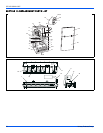
FURNACE CONTROL DIAGNOSTICS
The furnace has built-in, self-diagnostic capability. If a system problem
occurs, a blinking LED shows a fault code. The LED can flash red,
green or amber to indicate various conditions. It is located behind a
clear view port in the blower compartment door.
The control continuously monitors its own operation and the operation
of the system. If a failure occurs, the LED will indicate the failure code. If
the failure is internal to the control, the light will stay on continuously. In
this case, the entire control should be replaced, as the control is not
field repairable.
Flash sequence codes 1 through 10 are as follows: LED will turn “on”
for 1/4 second and “off” for 1/4 second. This pattern will be repeated the
number of times equal to the code. For example, six “on” flashes equals
a number 6 fault code. All flash code sequences are broken by a 2 sec-
ond “off” period.
SLOW GREEN FLASH: Normal operation.
SLOW AMBER FLASH: Normal operation with call for heat.
RAPID RED FLASH: Twinning error, incorrect 24V phasing. Check
twinning wiring.
RAPID AMBER FLASH: Flame sense current is below 1.5 microamps.
Check and clean flame sensor. Check for proper gas flow.
4 AMBER FLASHES: The control board is recieving a “Y” signal from
the thermostat without a “G” signal, indicating improper thermostat wir-
ing.
1 RED FLASH: This indicates that flame was sensed when there was
not a call for heat. With this fault code the control will turn on both the
inducer motor and supply air blower. A gas valve that leaks through or
is slow closing would typically cause this fault.
2 RED FLASHES: This indicates that the normally open pressure
switch contacts are stuck in the closed position. The control confirms
these contacts are open at the beginning of each heat cycle. This would
indicate a faulty pressure switch or miswiring.
3 RED FLASHES: This indicates the normally open pressure switch
contact did not close after the inducer was energized. This could be
caused by a number of problems: faulty inducer, blocked vent pipe, bro-
ken pressure switch hose or faulty pressure switch.
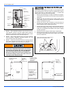
HOT SURFACE IGNITION SYSTEM
Do not attempt to light this furnace by hand (with a
match or any other means). There may be a potential
shock hazard from the components of the hot surface
ignition system. The furnace can only be lit automatically
by its hot surface ignition system.
Never bypass any safety control to allow furnace opera-
tion. To do so will allow furnace to operate under poten-
tially hazardous conditions.
Do not try to repair controls. Replace defective controls
with UPG Source 1 Parts.
Never adjust pressure switch to allow furnace operation.