


271015-UUM-A-0407
Unitary Products Group 5
FURNACE CLEANING SECTION
NOTE: The cleaning operations listed below must be performed only by
a qualified service agency.
Burner Removal/Cleaning
The main burners should be checked periodically for dirt accumulation.
If cleaning is required, follow this procedure:
1. Turn off the electrical power to the unit.
2. Turn off the gas supply at the external manual shut-off valve and
loosen the ground union joint.
3. Remove the upper access panel and remove the burner box
cover.
4. Disconnect wires from flame sensor, rollout switch and HSI igniter.
Remove igniter carefully, as it is easily broken.
5. Remove the screws that hold the burner box assembly to the vest
panel and remove the assembly.
6. Remove burners from the burner assembly.
7. Burners may be cleaned by rinsing in hot water.
8. Reassemble the burners in the reverse order.
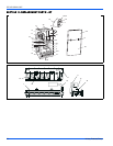
Cleaning the Heat Exchanger
Lower Heat Exchanger Access
1. Turn off the electrical power to the unit and turn off gas supply at
the shutoff valve.
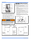
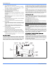
2. Remove the blower and burner compartment access doors. Dis-
connect the gas supply piping at the union to permit removal of the
entire burner and gas control assembly from the vestibule panel.
Use the wrench boss on the gas valve when removing or installing
this piping. See Figure 4.
3. Unplug the igniter from the wire harness. Disconnect sensor and
rollout switch wires located on top of the air shield. Identify and
note the location of all leads for ease of reinstallation. Also discon-
nect the wires at the side rollout switches (upflow only) and the
gas valve wires.
4. Remove the screws holding the burner assembly to the vestibule
panel and remove this assembly. Handle the assembly carefully
since it contains the igniter, which is fragile and easily broken. The
lower portion of the heat exchanger will now be exposed. To clean
the burner assembly, use a vacuum cleaner, or remove the burn-
ers as outlined in burner cleaning, and clean in hot water.
Upper Heat Exchanger Access
1. Perform steps 1-4 above.
2. Disconnect vent piping from the vent motor assembly at the top
panel on the furnace (upflow only). On downflow models, the vent
pipe is attached to the vent motor outlet. Remove this screw
before proceeding.
3. Unplug the vent motor wires and ground wire. Remove the pres-
sure switch tubing at the tap on the vent motor housing.
NOTE: It is recommended that replacement gaskets be available
before removing vent motor.
4. Remove six mounting screws that hold the vent motor to the
restrictor plate. The surface is gasketed and gasket can be reused
if it is carefully removed. It is necessary to remove this assembly to
gain access to the restrictor plate mounting holes. The assembly
may be vacuumed if cleaning is necessary. If any vent assembly
parts are damaged, replace with an entire new assembly (except
for gaskets).
5. Remove the perimeter screws attaching the restrictor plate assem-
bly to the vestibule panel. The surface is also gasketed. The
assembly, including the flue baffle plate (rear) may be vacuumed
or cleaned with hot water if necessary.
6. The upper portion of the heat exchanger is now accessible. With a
long flexible wire brush, clean inside each tube at both the top and
bottom. The brush must pass around the rear heat exchanger
tubes. Vacuum loose scale and dirt from each tube.
7. Clean - Replace all components in reverse order. Re-gasket all
surfaces which required a gasket. Reconnect all wiring. Reattach
vent pipe and gas supply lines before restoring service to furnace.
Restore electrical power, check gas supply piping for leaks, and
then verify furnace operation.
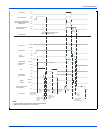
SEQUENCE OF OPERATION
The following describes the sequence of operation of the furnace. Refer
to Figure 1 for component location.
1. Call for 1st stage only
• On a call for 1st stage heat, the thermostat closes a circuit
between R and W1.
• The Microprocessor in the Furnace Control runs a ‘Self Check’.
• The Control checks the Primary Limit, Auxiliary Limit, and Roll-
out Switches for closed contacts.
• The Control checks that the Low Fire Pressure Switch (1LP) is
open.
• The Inducer Motor is energized on high speed, closing the con-
tacts of 1LP.
• The Control checks that 1LP is closed.
• The Igniter is energized for 17 seconds.
• The Gas Valve is energized on 1st Stage (Low Fire).
• Flame Rectification is recognized within 7 seconds.
• The Inducer is switched to low speed.
• 30 seconds after flame is proven, the ‘Heat Low’ relay is ener-
gized providing 120 Volts AC to the Blower Motor.
• At the same time, the EAC and Hum relays are energized, pro-
viding 120 Volts AC to the EAC Hot and Hum terminals.
2. Call for 2nd Stage after 1st Stage is operating
• A call for 2nd Stage can be made by a 2-Stage thermostat, or by
the W2 delay timer on the furnace control.
• The Inducer Motor is shifted to high speed by the control, closing
the contacts of 2LP (The High Fire Pressure Switch.).
• The Control checks that 2LP is closed.
• The Gas Valve is energized on 2nd Stage (High Fire).
• The Control simultaneously de-energizes the Heat Low relay
and energizes the Heat High relay, providing 120 Volts AC to a
different speed of the Blower Motor.
3. 2nd Stage is satisfied, 1st Stage still calling.
• If a Single Stage Thermostat is used, the Furnace will stay on
High Fire until the thermostat is satisfied.
• When the circuit between R and W2 is opened, the Control
switches the Inducer Motor to low speed, causing the contacts of
2LP to open.
• When 2LP opens, 2nd Stage of the Gas Valve is de-energized.
• 30 seconds later, the Control switches the Blower from Heat
High to Heat Low.
4. 1st Stage Satisfied
• The Thermostat opens the circuit between R and W1
• Immediately the Gas Valve is de-energized and Flame Rectifica-
tion is lost.
• The Inducer Motor is de-energized after a 15 second Post Purge
and the Hum terminal is de-energized.
• The ‘Fan Off Delay’ circuit is initiated. The Delay time can be
field set at 60, 90, 120, or 180 seconds. It comes from the fac-
tory set at 60 seconds.
• The Heat Low terminal is de-energized; stopping the Blower and
the EAC terminal is de-energized.
Label all wires prior to disconnection when servicing
controls. Wiring errors can cause improper and danger-
ous operation. Verify proper operation after servicing.