


271015-UUM-A-0407
6 Unitary Products Group
5. 1st and 2nd Stage called simultaneously
• The 1st stage call is processed as described in paragraph 1
above.
• Once Flame Rectification is established, 2nd Stage is entered
immediately as described in paragraph 2 above.
6. 1st and 2nd Stage satisfied simultaneously
• Both stages of the Gas Valve are de-energized.
• Flame Rectification is lost.
• The Inducer and Hum relays are de-energized after a 15-second
post purge.
• 30 seconds later the Control shifts the Blower from Heat High to
Heat Low.
• After the Blower-Off Delay Circuit is satisfied, the Blower and
EAC are de-energized.
7. Manual Fan Operation
• With the thermostat in the Fan On position, a circuit is completed
between R and G of the Control.
• The Heat Low and EAC relays are energized by the Control.
8. Call for Cooling
• The thermostat closes two circuits R to Y and R to G. Since the
Outdoor Unit is connected to Y and C at the Control, it is ener-
gized.
• The Cool and EAC relays are energized by the Control.
• A Blower-Off Delay Timing Circuit is energized by the call on Y.
9. Cooling call satisfied
• The thermostat opens the R to Y and R to G circuits.
• The Outdoor Unit is de-energized.
• The 60-second, Blower-Off Delay, timing circuit is initiated.
• After 60 seconds, the Cool and EAC relays are de-energized.
10. Two-stage cooling. This furnace is equipped to handle a two-stage
AC unit.
• The wall thermostat will energize the Y1 circuit for low cooling
and the Y2 circuit for high cooling.
CONTROL BOARD
Variable speed motors will adjust the motor speed in order to maintain
the indoor fan CFM. The control board is used to control the blower
speed thus the CFM when the unit is operating in the heating or cooling
modes. The blower CFM for cooling can be modified by changing the
jumper pin position on the taps selection marked COOL and ADJ.
The blower CFM for heating can be modified by changing the jumper
pin position on the taps selection marked HEAT. The taps selection pins
have been preset at the factory to provide the maximum CFM. “Air Flow
Data” table in the installation manual list the recommended jumper pin
settings.
If a lesser CFM is required for a specific HVAC system the taps selec-
tion pins can be moved to the "B", "C", or "D" positions. Pin "A" will pro-
vide the highest CFM and "D" will provide the lowest CFM. The taps
selection marked DELAY are used for cooling only. The recommended
settings for these jumper pins are listed in Delay taps selection.
HEATING AIRFLOW
The heating airflow has been preset at the factory to provide maximum
CFM. If a lesser CFM is required for a specific HVAC system the
“JUMPER” on the HEAT selection pins on the control board may be
moved to tap “B”, “C”, or “D”.
HEAT Taps Selection on the control board.
Pin Position A: will provide the highest CFM.
Pin Position B and C: are the medium and medium low CFM settings.
Pin Position D: will provide the lowest CFM.
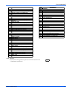
Refer to “Air Flow Data” table in the installation manual for the
proper “HEAT” Taps Selection for the model furnace you are
installing.
NOTE: When changing jumper positions, make sure that the jumper is
pushed all the way on the pins. If the jumper is not making good contact
or is left off completely, the blower will operate as if the jumper were in
the “A” position.
NOTE: Power to the blower must be removed for at least 4 seconds
after a heat or cool tap selection change, in order for the motor to recog-
nize an adjustment. The fixed blower on delay and adjustable blower-off
delay will function as described in the “OPERATION AND MAINTE-
NANCE" Section in the Users Information Manual.
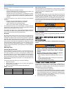
ADJUSTMENT OF FAN CONTROL SETTINGS
Heating Indoor Fan Off Delay
Changing the blower delay jumper on the Furnace Control Board can
change the indoor fan “OFF” time delay. Refer to Figure 6 for the jumper
settings to obtain the desired fan OFF delay. The blower off delay must
be long enough to adequately cool the furnace, but not so long that cold
air is blown into the living space.
The blower on delay is fixed at 30 seconds and cannot be adjusted.
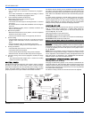
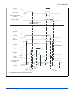
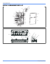
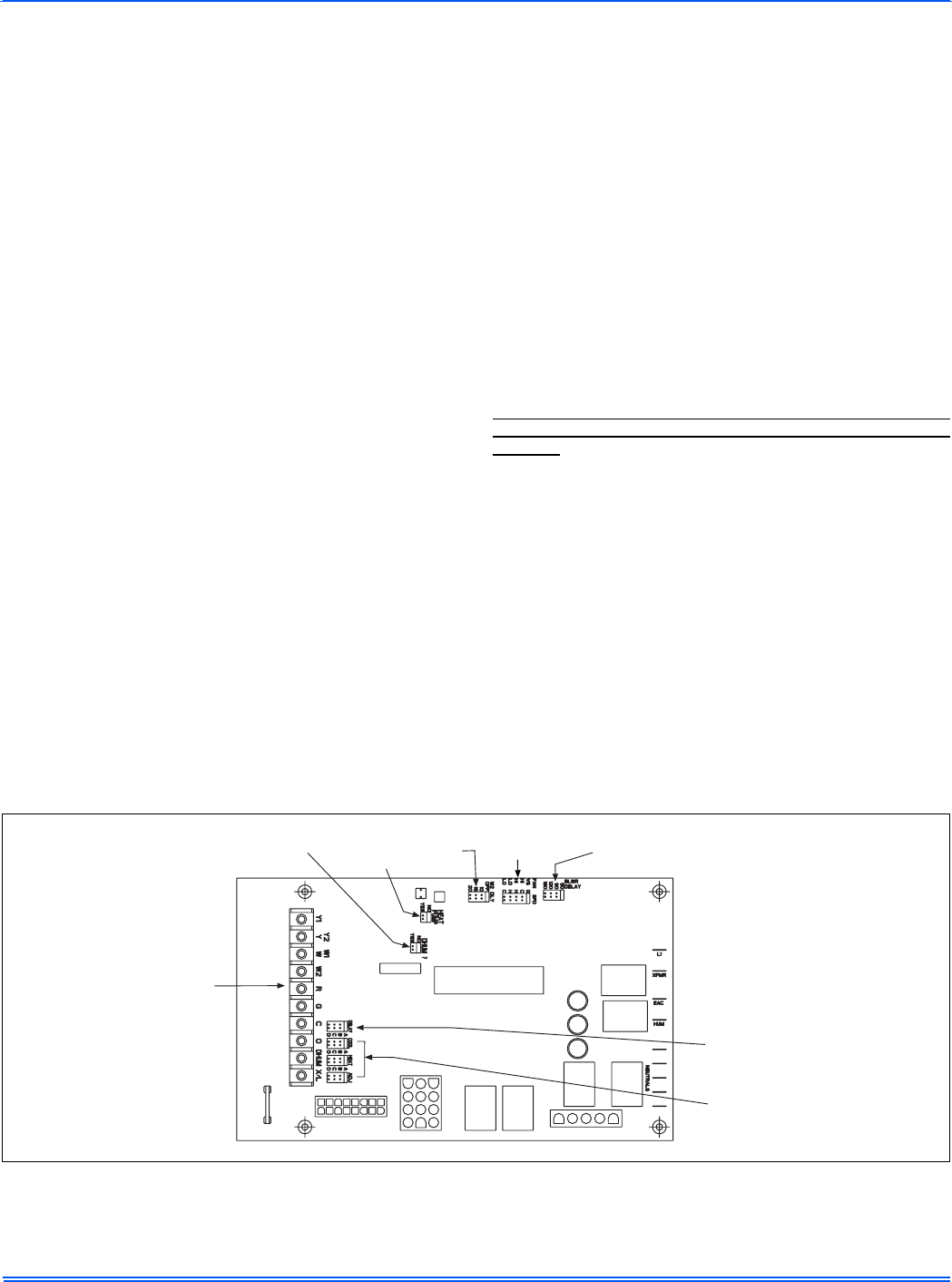
FIGURE 6: Furnace Control Board
CONTINUOUS
FAN SPEED
JUMPER
BLOWER
OFF DELAY
JUMPER
HI HEAT
DELAY
JUMPER
HEAT
DELAY
JUMPER
DEHUMIDISTAT
JUMPER
LOW
VOLTAGE
TERMINALS
BLOWER
SPEED
JUMPERS
COOLING
PROFILE
JUMPER