


262260-YTG-E-1008
40 Johnson Controls Unitary Products
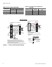
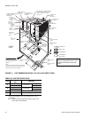
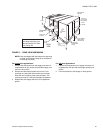
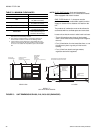
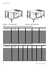
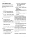
FIGURE 14 - TYPICAL ROOFTOP INSTALLATION
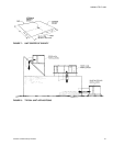
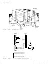
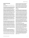
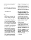
FIGURE 15 - TYPICAL SIMPLICITY
®
CONTROL WIRING DIAGRAM
W1
W2
Y1
G
OCC
P
P1
Y2
X
R
SD
C
C
SD
SD
R
OCC
C
RC
G
Y2
Y1
W2
W1
Jumper
Smoke
Detector
24 VAC
Class 2
X
R
THERMOSTAT
TERMINALS
CONTROL
TERMINAL
BLOCK
TERMINALS ON
A LIMITED
NUMBER OF
THERMOSTATS
3
1
2
4
3
1
2
4
Second stage heating not required on single stage heating units.
Second stage cooling not required on single stage cooling units.
Jumper is required if there is no Smoke Detector circuit.
Jumper is required for any combination of R, RC, or RH.
6
5
5
6
OCC is an output from the thermostat to indicate the Occupied condition.
X is an input to the thermostat to display Error Status conditions.