


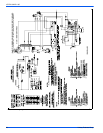
107272-UIM-B-1105
32 Unitary Products Group
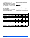
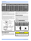
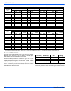
Table shows 4% Input Reduction per 1,000 ft. (304.8 m) Elevation. Reference Source: NFPA No. 54, ANSI Z 223.1, National Fuel Gas Code.
For Canadian high altitude {2000 - 4500 ft. (609.6 - 1,371.6)}, reduce gas manifold pressure to 3.0” w.c. (0.75 kPa) for Natural gas and for Propane gas.
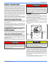
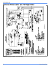
SIZING FURNACE INPUT
The orifice spud supplied with all burners is the size for the minimum
BTU input of the burner for the type gas shown on the rating plate.
Table 18 shows the correct drill size for various inputs.
The correct manifold pressure for natural and LP gas is 3.5" w.c (0.87
kPa). Only minor adjustments in the input rate should be made by
adjusting the pressure regulator. The minimum manifold pressure
should be 3.0" w.c. (0.75 kPa) and the maximum pressure should be
3.5 w.c. (0.87 kPa) the next size larger or smaller orifice size should be
used if the desired input rating cannot be obtained within the above
manifold pressure adjustment range.
NOTE: The BTU input valves in the above table show the approximate
hourly input of the burner for the various drill sizes shown. To determine
the actual input of the burner, turn off all other gas appliances.
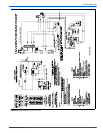
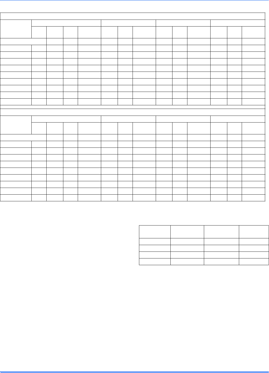
TABLE 18:
High Altitude Duration Chart
NATURAL GAS
Elevation
Feet
56,000 — Input 70,000 — Input 77,000 — Input 90,000 — Input
Meters
Orifice
Dia.
Drill
Size
Part #
Orifice
Dia.
Drill
Size
Part #
Orifice
Dia.
Drill
Size
Part #
Orifice
Dia.
Drill
Size
Part #
Sea Level 0.136 29 9951--1361 0.154 23 9951--1541 0.161 20 9951--1611 0.180 15 9951--1801
2,000 618 0.136 29 9951--1361 0.149 25 9951--1491 0.157 22 9951--1571 0.177 16 9951--1771
3,000 914 0.128 30 9951--1281 0.149 25 9951--1491 0.157 22 9951--1571 0.173 17 9951--1731
4,000 1219 0.128 30 9951--1281 0.147 26 9951--1471 0.154 23 9951--1541 0.173 17 9951--1731
5,000 1524 0.128 30 9951--1281 0.144 27 9951--1441 0.152 24 9951--1521 0.169 18 9951--1691
6,000 1829 0.128 30 9951--1281 0.144 27 9951--1441 0.149 25 9951--1491 0.166 19 9951--1661
7,000 2134 0.120 31 9951--1201 0.140 28 9951--1401 0.147 26 9951--1471 0.161 20 9951--1611
8,000 2438 0.120 31 9951--1201 0.136 29 9951--1361 0.144 27 9951--1441 0.161 20 9951--1611
9,000 2743 0.120 31 9951--1201 0.136 29 9951--1361 0.140 28 9951--1401 0.157 22 9951--1571
10,000 3048 0.116 32 9951--1161 0.128 30 9951--1281 0.136 29 9951--1361 0.152 24 9951--1521
PROPANE GAS
Elevation
Feet
56,000 — Input 70,000 — Input 77,000 — Input 90,000 — Input
Meters
Orifice
Dia.
Drill
Size
Part #
Orifice
Dia.
Drill
Size
Part #
Orifice
Dia.
Drill
Size
Part #
Orifice
Dia.
Drill
Size
Part #
Sea Level 0.082 45 9951--0821 0.093 42 9951--0931 0.098 40 9951--0981 0.106 36 9951--1061
2,000 618 0.081 46 9951--0811 0.093 42 9951--0931 0.096 41 9951--0961 0.104 37 9951--1041
3,000 914 0.078 47 9951--0781 0.089 43 9951--0891 0.093 42 9951--0931 0.101 38 9951--1011
4,000 1219 0.078 47 9951--0781 0.089 43 9951--0891 0.093 42 9951--0931 0.101 38 9951--1011
5,000 1524 0.078 47 9951--0781 0.089 43 9951--0891 0.093 42 9951--0931 0.099 39 9951--0991
6,000 1829 0.076 48 9951--0761 0.086 44 9951--0861 0.089 43 9951--0891 0.098 40 9951--0981
7,000 2134 0.076 48 9951--0761 0.086 44 9951--0861 0.089 43 9951--0891 0.096 41 9951--0961
8,000 2438 0.073 49 9951--0731 0.082 45 9951--0821 0.086 44 9951--0861 0.096 41 9951--0961
9,000 2743 0.073 49 9951--0731 0.081 46 9951--0811 0.086 44 9951--0861 0.093 42 9951--0931
10,000 3048 0.070 50 9951--0731 0.078 47 9951--0781 0.082 45 9951--0821 0.089 43 9951--0891
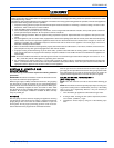
TABLE 19:
Gas Burner Settings
Gas
(@ 3.5” W.C.)
Firing Rate
BTU/Hr (kw)
Orifice
Size
Air Shutter
Setting
Natural 66,000 (19.3) 0.142” (3.61mm) 1.0
Natural 84,000 (24.6) 0.166” (4.22 mm) 3.5
LP 66,000 (19.3) 0.116” (2.95 mm) 2.0
LP 84,000 (24.6) 0.100” (2.54 mm) 3.5