


107272-UIM-B-1105
Unitary Products Group 11
IMPORTANT: Air velocity through throwaway type filters must not
exceed 300 feet per minute (1.52 m/m).
.
.
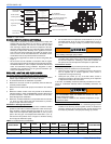
SECTION IV: OIL PIPING
OIL SAFETY
IMPORTANT INFORMATION: Long or oversized inlet lines may require
the pump to operate dry during initial bleeding period. In such cases,
the priming may be assisted by injecting fuel oil in the pump gearset.
Under lift conditions, lines and fittings must be air tight. To assure this,
“Pipe Dope” may be applied to both the used and unused inlet and both
return fittings. DO NOT USE TEFLON TAPE! DO NOT USE COM-
PRESSION FITTINGS!
VACUUM CHECK: A vacuum gauge may be installed in either of the 1/
4” NPT inlet ports. The Beckett CleanCut pump should be used where
the vacuum does not exceed 6” hg. (20.3 kPa) single pipe and 12” hg.
(40.6 kPa) two pipe. Remember, running vacuum is the total of all pres-
sure drops (∆P) in the system from tank to inlet of pump.
PRESSURE CHECK: When a pressure check is made, use either the
BLEED PORT OR NOZZLE PORT.
CUTOFF CHECK: To check cut-off pressure, dead head a pressure
gauge in nozzle port. Run burner for short period of time. Shut burner
off. The pressure will drop and hold above zero
.
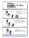
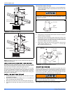
CONNECT FUEL LINES
Carefully follow the fuel unit manufacturer’s literature and the latest edi-
tion of NFPA 31 for oil supply system specifications. If this information is
unavailable, use the following basic guidelines.
Fuel Supply Level With or Above Burner
The burner may be equipped with a single-stage fuel unit for these
installations. Connect the fuel supply to the burner with a single supply
line if you want a one-pipe system (making sure the bypass plug is NOT
installed in the fuel unit). Manual venting of the fuel unit is required on
initial start-up. If connecting a two-pipe fuel supply, install the fuel unit
bypass plug.
Fuel Supply Below the Level of the Burner
When the fuel supply is below the level of the burner, a two-pipe fuel
supply system is required. Depending on the fuel line diameter and hor-
izontal and vertical length, the installation may also require a two-stage
pump. Consult the fuel unit manufacturer’s literature for lift and vacuum
capability.
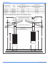
Fuel Line Installation
• Continuous lengths of heavy wall copper tubing are recom-
mended. Always use flare fittings. Never use compression fit-
tings.
• Always install fittings in accessible locations. Fuel lines should
not run against the appliance or the ceiling joists (to avoid vibra-
tion noise).
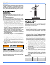
Fuel Line Valve and Filter
Install two high quality shut-off valves in accessible locations on the oil
supply line. Locate one close to the tank and the other close to the
burner, upstream of the filter.
Install a generous capacity filter inside the building between the fuel
tank shut-off valve and the burner, locating both the filter and the valve
close to the burner for ease of servicing. The filter should be rated for
50 microns 50 micrometers) or less.
All installations must have a filter installed.
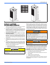
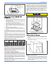
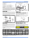
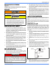
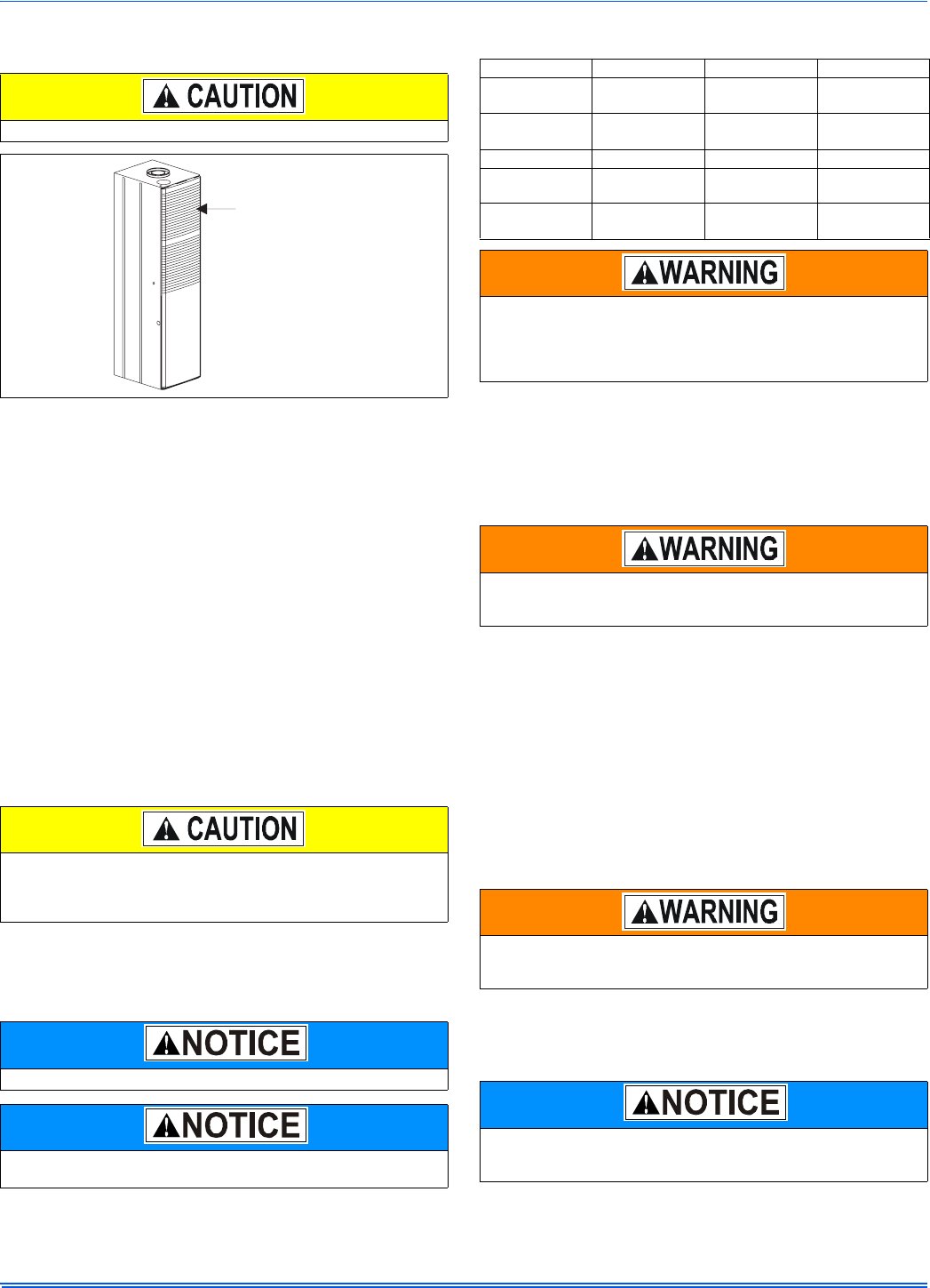
FIGURE 15: Furnace Air Filters
Pressurized or gravity feed installations must not exceed 3 P.S.I.
20.7 kPa) on inlet line or return line at the pump per NFPA 31. A
pressure greater than 10 P.S.I. (69.0 kPa) may cause damage to
the shaft seal.
Fuel units with automatic bypass do not require a bypass plug.
Burners equipped with a Beckett CleanCut pump must have a con-
trol system that provides a valve-on delay (prepurge).
Air Filters Can Be
Found On The Inside
Of ThisAccess Panel
TABLE 6:
Burner Specifications
Furnace Model Burner Spec ATC Head
DFAA084BBTA
DFAH084BBSA
EVC - 201 AF36YHHS F3
DFAA066BBTA
DFAH066BBSA
EVC - 202 AF36YHHS F3
Static Plate Nozzle Pump Pressure Air Boot Setting
3-3/8 U 0.65 x 70° A
Delavan
100 psi
(689.5 kPa)
4.0
3-3/8 U 0.50 x 70° A
Delavan
100 psi
(689.5 kPa)
3.0
The burner fuel unit is shipped without the bypass plug installed.
You must install this plug on two-pipe oil systems. DO NOT install
the plug in the fuel unit if connected to a one-pipe oil system. Fail-
ure to comply could cause fuel unit seal failure, oil leakage, and
potential fire and injury hazard.
The oil supply inlet pressure to the fuel unit cannot exceed 3 psi.
(20.7 kPa) Install a pressure-limiting device in accordance with
NFPA 31.
Never use Teflon tape on any fuel fitting. Tape fragments can lodge
in fuel line components and the fuel unit, damaging the equipment
and preventing proper operation.
Some states require these valves to be fusible-handle design for
protection in the event of fire. We recommend this as good industry
practice for all installations.