


107272-UIM-B-1105
22 Unitary Products Group
FAN-ASSISTED COMBUSTION SYSTEM
An appliance equipped with an integral mechanical means to either
draw or force products of combustion through the combustion chamber
and/or heat exchanger.
SECTION VII: SAFETY CONTROLS
CONTROL CIRCUIT FUSE
A 3-amp fuse is provided to protect the 24-volt transformer from over-
load caused by control circuit wiring errors. This is an ATO 3, automo-
tive type fuse and is located in the control box.
LIMIT CONTROLS
There is a high temperature limit control located on the furnace vesti-
bule panel near the control box. This is an automatic reset control that
provides over temperature protection due to reduced airflow, that may
be caused by a dirty filter, or if the indoor fan motor should fail.
INDOOR FAN SWITCH
The indoor fan motor is an operation controlled by normally open tem-
perature actuated switch located above the limit control which is set to
close at 110° F (43.3° C) and open at 90° F (32.2° C).
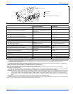
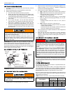
OIL BURNER PRIMARY CONTROL
The R7184A, B, P, U Interrupted Electronic Oil Primary is a line voltage,
safety rated, interrupted ignition oil primary control for residential oil
fired burners used in forced air furnaces. The R7184A, B, P, U used
with a cad cell flame sensor operates an oil burner and optional oil
valve. The primary controls fuel oil, senses flame, controls ignition
spark and notifies a remote alarm circuit when in lockout.
The indicator light on the oil primary control provides lockout, recycle,
and cad cell indications as follows:
1. Flashing at 1/2 second on, 1/2 second off: system is locked out or
in restricted mode.
2. Flashing at 2 seconds on, 2 seconds off: control is in recycle
mode.
3. On: cad cell is sensing flame.
4. Off: cad cell is not sensing flame.
Cad Cell Resistance Check
For proper operation, it is important that the cad cell resistance is below
1600 ohms. During a normal call for heat, once the control has entered
the Run mode, press and release the reset button. See Table 10 for
equivalent cad cell resistance.
Preliminary Steps
1. Check wiring connections and power supply.
2. Make sure power is on to controls.
3. Make sure limit control is closed.
4. Check contacts between ignitor and the electrodes.
5. Check the oil pump pressure.
6. Check the piping to the oil tank.
7. Check the oil nozzle, oil supply and oil filter.
Check Oil Primary Control
If the trouble is not in the burner or ignition hardware, check the oil pri-
mary control by using the following equipment:
1. Screwdriver
2. Voltmeter (0 to 150 VAC range)
3. Insulated jumper wire with both ends stripped
4. Refer to the trouble shooting guide located after the wiring dia-
grams to determine failure.
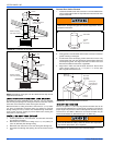
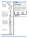
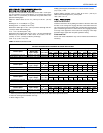
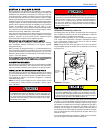
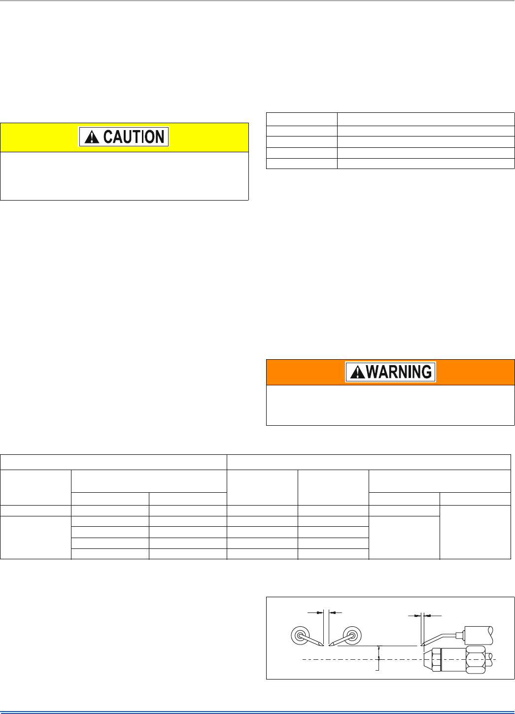
Check / Adjust Electrodes
Check the electrode tip settings. Adjust, if necessary, to comply with the
dimensions shown in Figure 35. To adjust, loosen the electrode clamp
screw and slide/rotate the electrodes as necessary. Securely tighten the
clamp screw when finished.
Main power to the unit must still be interrupted at the main power
disconnect switch before any service or repair work is to be done to
the unit.
Blower and burner must never be operated without the blower
panel in place.
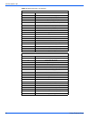
TABLE 10:
Cad Cell Resistance When Sensing Flame
Flashes Cad Cell Resistance in Ohms
1 Less than 400
2 More than 400 and less than 800
3 More than 800 and less than 1600
4 More than 1600 and less than 5000
Electrical Shock Hazard
Can cause severe injury, death or property damage.
Be careful to observe all precautions to prevent electrical shock or
equipment damage.
TABLE 11:
Timings and Settings
Delay Timings
a
DIP Switch Settings
Valve-On Delay
(seconds)
Burner Motor-Off Delay
(minutes)
S-1 S-2
S-3 Enable / Disable
R7184U R7184P R7184U R7184P
00 —XXOff
b
15
00.5OffOff
On
22OffOn
4 4 On Off
5 8 On On
X No Difference or Impact
a
Specific models may have different timings. Be sure to check device label.
b
S-3 not provided on R7184P models.
FIGURE 35: Electrode Settings
1/16"
Nozzle-to-tip
Spacing
5/32"
Gap
END VIEW
SIDE VIEW
5/16” Above Nozzle Center