


036-21359-001-B-0302
Unitary Products Group 9
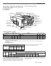
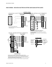
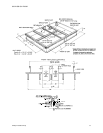
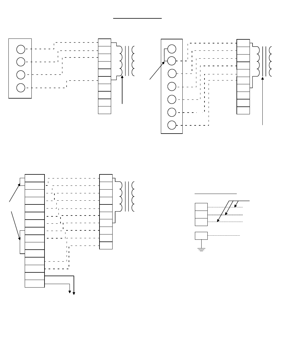
FIELD WIRING - DCE/DCG ELECTRIC/ELECTRIC AND GAS/ELECTRIC UNITS
R
Y1
Y2
W1
G
B
X
A1
A2
G
R
Y1
Y2
R
Y1
Y2
W1
G
B
X
A1
A2
RH
RC
Y1
Y2
W1
W2
G
W2
W2
R
Y1
Y2
W1
G
B
X
A1
A2
W2
T
T
A2
A1
COM
LED 2
LED 1
B
G
W2
W1
Y2
Y1
RH
RC
ADD
JU M PER
24 VO LT
TRANSFORM ER
24 VO LT
TRANSFORM ER
24 VO LT
TRANSFORM ER
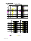
C O O L IN G O N L Y (2 4 V O L T T H E R M O S T A T )
UNIT TERMINAL
BLOCK 1TB
2
THERMOSTAT
1
TERM INALS
C O O L IN G / H E A T IN G (2 4 V O L T T H E R M O S T A T )
THERMOSTAT
1
TERM INALS
UNIT TERMINAL
BLOCK 1TB
2
1
24 Volt Therm ostat 2TH04701224.
2
Term inal block 1TB - located on relay board in 24-volt section
of the unit control box.
1
24 Volt Therm ostat 2TH04701024 or 2TH04701524
(with subbase 2TB04700224 or 2TB04700324).
2
Term inal block 1TB - located on relay board in 24-volt section
o f th e u n it co n tro l b o x.
3
Second stage heating is not required on units with a single stage
electric heater.
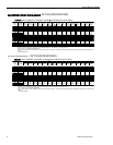
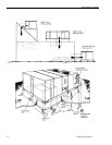
C O O L IN G / H E A T IN G (E L E C T R O N IC T H E R M O S T A T )
THERMOSTAT
1
TERM INALS
UNIT TERMINAL
BLOCK 1TB
2
3
3
4
4
1
Electronic program m able Therm ostat 2ET04700224 (includes subbase).
2
Term inal block 1TB - located on relay board in 24-volt section of the unit control box.
3
Second stage heating is not required on units with a single stage electric heater.
4
Term inals A1 and A2 provide a relay output to close the outdoor econom izer dam pers
when the therm ostat switches to the set-back position.
TO REMOTE SENSOR
2TH04702224 IF USED
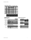
L1
L2
L3
O
R e fe r to th e
ELECTRICAL
DATA
ta b le s to s ize th e
power wiring, the
fuses and the
disconnect
sw itch.
LINE VOLTAGE
TERM INAL
BLOCK 2TB
IN U N IT
CONTROL BOX
GROUND LUG
Fan switch m ust be in "ON" position for m inim um ventilation during heater operation.
CONTROL W IRING
ADD
JUMPER
NOT
USED
POW ER W IRING