


036-21359-001-B-0302
10 Unitary Products Group
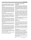
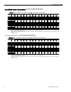
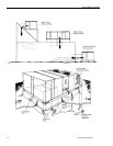
RETURN
AIR
SUPPLY
AIR
BOTTOM SUPPLY
AND RETURN
AIR OPENINGS
(See Note)
(B)
POWER WIRING
ENTRY
(A)
CONTROL WIRING
ENTRY
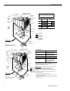
NOTE:
For curb mounted units, refer to the curb hanger
dimensions of the curb for the proper size of the
supply and return air duct connections.
UNIT BASE WITH RAILS
Shown separately to illustrate
Bottom Duct openings and Power
Connection locations
12-1/2"
9-1/4"
8-1/8"
9-3/4"
3-3/4"
(B)
POWER WIRING
ENTRY
(A)
CONTROL WIRING
ENTRY
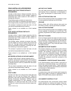
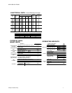
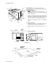
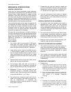
92"
CONDENSER
COILS
OPTIONAL COIL
GUARD KIT
COMPRESSOR
ACCESS
(See detail "X")
ECONOMIZER / MOTORIZED DAMPER,
FIXED OUTDOOR INTAKE AIR AND
POWER EXHAUST RAIN HOODS
(See detail "Y")
FIELD-SUPPLIED
DISCONNECT SWITCH
LOCATION
BLOWER
ACCESS
BLOWER MOTOR
ACCESS
BLOWER
COMPARTMENT
ACCESS
(Auxiliary)
DOT PLUG
(For pressure
Drop Reading)
FRONT
VIEW
ELECTRIC HEAT
ACCESS
CONTROL BOX
ACCESS
21"
5"
9-3/4"
11-1/2"
2-3/4" 21-1/2"
33"
35"
5-7/8"
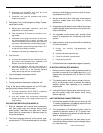
RETURN AIR
SUPPLY AIR
OUTDOOR AIR
OUTDOOR AIR
(Economizer)
24-1/4" (15 TON)
36-1/4" (20 TON)
48-5/8" (15TON)
52-5/8" (20TON)
125-1/4" (15 TON)
136-1/4" (20 TON)
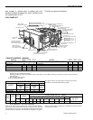
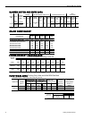
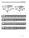
HOLE
OPEN ING
SIZE
(DIA.)
USED FOR
A
1-1/8" KO Con trol
Wir ing
Front
3/4" NPS (Fem.) Bot tom
B
3-5/8" KO
Power
Wir ing
Front
3" NPS (Fem.) Bot tom
C 2-3/8" KO Gas Pip ing (Front)
1
D 1-11/16" Hole
Gas Pip ing (Bot -
tom)
1,2
1
1" pip ing MPT re quired
2 Open ing in the bot tom of the unit can be lo cated by the slice
in the in su la tion.
UTILITIES ENTRY DATA
All dimensions are in inches. They are
subject to change without notice. Certified
dimensions will be provided upon request.
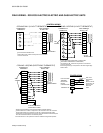
RETURN
AIR
SUPPLY
AIR
BOTTOM SUPPLY
AND RETURN
AIR OPENINGS
(See Note)
(B)
POWER WIRING
ENTRY
(A)
CONTROL WIRING
ENTRY
NOTE:
For curb mounted units, refer to the curb hanger
dimensions of the curb for the proper size of the
supply and return air duct connections.
UNIT BASE WITH RAILS
Shown separately to illustrate
Bottom Duct openings, Power
and Gas Piping Connection
locations
12-1/2"
9-1/4"
8-1/8"
9-3/4"
3-3/4"
(B)
POWER WIRING
ENTRY
(A)
CONTROL WIRING
ENTRY
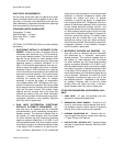
92"
CONDENSER
COILS
OPTIONAL
COIL GUARD
KIT
COMPRESSOR
ACCESS
(See detail "X")
ECONOMIZER / MOTORIZED DAMPER,
FIXED OUTDOOR INTAKE AIR AND
POWER EXHAUST RAIN HOODS
(See detail "Y")
FIELD-SUPPLIED
DISCONNECT SWITCH
LOCATION
BLOWER
ACCESS
BLOWER MOTOR
ACCESS
BLOWER
COMPARTMENT
ACCESS
(Auxiliary)
DOT PLUG
(For pressure
Drop Reading)
FRONT
VIEW
CONTROL BOX
ACCESS
21"
5"
9-3/4"
11-1/2"
2-3/4" 21-1/2"
33"
35"
5-7/8"
46-5/8"
7-1/8"
6-3/8"
VENT AIR
OUTLET
HOODS
COMBUSTION
AIR INLET
HOOD
GAS HEAT
ACCESS
(C)
GAS SUPPLY
ENTRY
46-5/8"
11-1/8"
(D)
GAS SUPPLY
ENTRY
35-1/4
136-1/4
52-5/8
RETURN AIR
SUPPLY AIR
OUTDOOR AI
R
OUTDOOR AI
R
(Economizer)
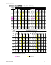
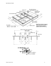
Front 36"
Back
24" (Less Econo mizer)
49" (With Econo mizer)
Left Side (Fil ter Ac cess)
24" (Less Econo mizer)
36" (With Econo mizer)
Right Side (Cond. Coil) 36"
Be low Unit
1
20"
Above Unit
2
72" With 36" Maxi mum
Hori zon tal Over hang
(For Con denser Air
Dis charge)
1U nits (ap pli ca ble in U.S.A. only) may be in stalled on com bus ti ble floors
made from wood or class A, B or C roof cov er ing ma te rial.
2
Units must be in stalled ou doors. Over hang ing struc tures or shrubs should
not ob struct con denser air dis charge out let.
NOTE:
ELEC/ELEC Mod els
: Units and duct work are ap proved for zero clear ance to
com bus ti ble ma te ri als when equipped with elec tric heat ers.
GAS/ELEC Mod els: A 1" clear ance must be pro vided be tween any
com bus ti ble ma te rial and the sup ply air duct work for a dis tance of 3 feet
from the unit.
The prod ucts of com bus tion must not be al lowed to ac cu mu late within a
con fined space and re cir cu late.
Lo cate unit so that the vent air out let hood is at least:
? Three (3) feet above any forced air in let lo cated within 10 hori zon tal feet (ex -
clud ing those in te gral to the unit).
? Four (4) feet be low, 4 hori zon tal feet from, or 1 foot above any door or grav ity
air in let into the build ing.
CLEARANCES