


036-21630-001-B-0904
30 Unitary Products Group
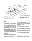
lated with a minimum 1/2” thick insulation, coated on the air-
side. Aluminum foil faced insulation shall be used in the
furnace compartment and be fastened with ridged fasteners
to prevent insulation from entering the air stream. Cabinet
panels shall be “large” size, easily removable for servicing
and maintenance. Full perimeter base rails shall be provided
to assure reliable transit of equipment, overhead rigging and
proper sealing on roof curb applications. Disposable 1" filters
shall be furnished and be accessible through a removable
access door, sealed airtight. Units filter track shall be
designed to accommodate either 1” or 2” filters. Fan perfor-
mance measuring ports shall be provided on the outside of
the cabinet to allow accurate air measurements of evaporator
fan performance without removing panels or creating air by-
pass of the coils. Condensate pan shall be internally sloped
and conform to ASHRAE 62-89 self-draining standards. Con-
densate connection shall be a minimum of 3/4” I.D. female
and be a ridged mount connection.
INDOOR (EVAPORATOR) FAN ASSEMBLY
The indoor fan shall be a factory installed belt drive assembly
that includes an adjustable pitch motor pulley. Job site
selected (B.H.P.) brake horsepower shall not exceed the
motors nameplate horsepower rating, plus the service factor.
Units shall be designed not to operate above service factor.
Fan wheel shall be double-inlet type with forward-curved
blades, dynamically balanced to operate smoothly throughout
the entire range of operation. Airflow design shall be constant
air volume. Bearings shall be sealed and permanently lubri-
cated for longer life and no maintenance.
OUTDOOR (CONDENSER) FAN ASSEMBLY
The outdoor fan shall be of the direct-driven propeller type,
discharge air vertically, have aluminum blades riveted to a
corrosion resistant steel spider bracket and shall be dynami-
cally balanced for smooth operation. The outdoor fan motor
shall be totally enclosed with permanently lubricated bear-
ings, internally protected against overload conditions and
staged independently.
REFRIGERANT COMPONENTS
Compressor:
a. Shall be internally protected with internal high-pres-
sure relief and over temperature protection.
b. Shall have internal spring isolation and sound muf-
fling to minimize vibration and noise, and be exter-
nally isolated on a dedicated, independent
mounting.
Coils:
a. Evaporator and condenser coils shall have alumi-
num plate fins mechanically bonded to seamless
internally enhanced copper tubes with all joints
brazed. Special Phenolic coating shall be available
as a factory option.
b. Evaporator and Condenser coils shall be of the
direct expansion, draw-thru, design.
Refrigerant Circuit and Refrigerant Safety Components shall
include:
a. Independent fixed-orifice expansion devices.
b. Filter drier/strainer to eliminate any moisture or for-
eign matter.
c. Accessible service gage connections on both suc-
tion and liquid lines to charge, evacuate, and mea-
sure refrigerant pressure during any necessary
servicing or troubleshooting without losing charge.
d. The refrigeration system shall provide at least 15°F
of sub-cooling at design conditions.
UNIT CONTROLS
a. Unit shall be complete with self-contained low-volt-
age control circuit protected by a resetable circuit
breaker on the 24-volt transformer side.
b. Unit shall incorporate a lockout circuit which pro-
vides reset capability at the space thermostat or
base unit, should any of the following standard
safety devices trip and shut off compressor.
c. Loss-of-charge/Low-pressure switch.
d. High-pressure switch.
e. Freeze-protection thermostat, evaporator coil.
f. If any of the above safety devices trip, a LED (light-
emitting diode) indicator shall flash a diagnostic
code that indicates which safety switch has tripped.
g. Unit shall incorporate “AUTO RESET” compressor
over temperature, over current protection.
h. Unit shall operate with conventional thermostat
designs and have a low voltage terminal strip for
easy hook-up.
i. Unit control board shall have on-board diagnostics
and fault code display.
j. Standard controls shall include anti-short cycle and
low voltage protection, and permit cooling operation
down to 0°F.
k. Control board shall monitor each refrigerant safety
switch independently.
l. Control board shall retain last 5 fault codes in non
volatile memory, which will not be lost in the event of
a power loss.
ELECTRIC HEATING SECTION
An electric heating section, with nickel chromium elements,
shall be provided in a range of 5 thru 30 KW, offering two
stages of capacity - 16 KW and above on 208/230 volt heat-
ers and 20 KW and above on 460 and 575 volt heaters. The
heating section shall have a primary limit control(s) and auto-