


GENERAL DESCRIPTION
Units shall be factory--assembled, single packaged Heat
Pumps, designed for outdoor mounted installation. Units shall
have minimum SEER ratings of 10.0. They shall have built in
field convertible duct connections for down discharge
supply/return or horizontal discharge supply/return, and be
available with factory installed options or field installed
accessories.
The units shall be factory wired, piped, charged with R--22
refrigerant and factory tested prior to shipment. All unit wiring
shall beboth numberedand colorcoded. Enclosedin eachunit
shall be a factory test log sheet consisting of the unit tested
pressures, temperatures and amps, as tested prior to
shipment.
All units shallbe manufacturedin a facilitycertified toISO 9001
standards, and the cooling & heating performance shall be
rated in accordance with DOE and ARI test procedures. Units
shall be listed under UL 1995/CAN/CSA No. 236--M90
conditions.
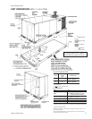
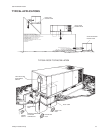
UNIT CABINET
1. Unit cabinet shall be constructed of G90 galvanized
steel, with exterior surfaces coated with a non--chalking,
powered paint finish, certified at 750 hours salt spray test
per ASTM--B117 standards.
2. Indoor blower section shall be insulated with up to 1"
thick insulation, coated on the air side. Aluminum foil
faced insulation shall be used in the furnace compart-
ment and be fastened with ridged fasteners to prevent in-
sulation from entering the air stream.
3. Cabinet panels shall be “large” size, easily removable for
servicing and maintenance.
4. Full perimeter base rails shall be provided to assure reli-
able transit of equipment, overhead rigging, fork truck ac
-
cess and proper sealing on roof curb applications.
5. Disposable 1" filters shall be furnished and be accessible
through a removable access door, sealed air tight. Units
filter track shall be designed to accommodate either 1" or
2" filters.
6. Fan performance measuring ports shall be provided on
the outside of the cabinet to allow accurate air measure
-
ments of evaporator fan performance without removing
panels or creating air by--pass of the coils.
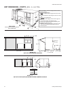
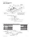
7. Units vertical discharge and return duct configuration
shall be designed to fit between standard 24" O.C.
beams without modification to building structure, duct
work and base unit.
8. Condensate pan shall be internally sloped and conform
to ASHARE 62--89 self--draining standards. Condensate
connection shall be a minimum of 3/4" I.D. female and be
a ridged mount connection.
INDOOR (SUPPLY) FAN ASSEMBLY
1. Fan shall be direct drive, multi--speed, or a factory in
-
stalled belt drive, adjustable--pitch motor pulley option.
Job site selected (BHP) brake horse power shall not ex
-
ceed the motors nameplate horse power rating, plus the
service factor. Units shall be designed not to operate
above service factor.
2. Fan wheel shall be double--inlet type with forward--
curved blades, dynamically balanced to operate
smoothly throughout the entire range of operation.
Airflow design shall be constant air volume.
3. Bearings shall be sealed and permanently lubricated for
longer life and no maintenance.
OUTDOOR FAN ASSEMBLY
1. The outdoor fan shall be of the direct--driven propeller
type, discharge air vertically, have aluminum blades
riveted to corrosion resistant steel spider bracket and
shall be dynamically balanced for smooth operation.
2. The outdoor fan motor shall be totally enclosed with
permanently lubricated bearings and internally protected
against overload conditions.
REFRIGERANT COMPONENTS
1. Compressors:
A. Shall be fully hermetic type, direct drive, internally pro
-
tected with internal high--pressure relief and over tem
-
perature protection. The hermetic motor shall be
suction gas cooled and have a voltage range of + or --
10% of the unit nameplate voltage.
B. Shallhave internalisolation andsound mufflingto mini-
mize vibration and noise, and be externally isolated on
a dedicated, independent mounting.
2. Coils:
A. Evaporator and condenser coils shall have aluminum
plate finsmechanically bonded toseamless internally--
enhanced copper tubes with all joints brazed. Special
Phenoliccoatingshall beavailableasafactoryoption.
B. Evaporator and Condenser coils shall be of the direct
expansion, draw--thru design.
3. Refrigerant Circuit and Refrigerant Safety Components
shall include:
A. Independent fixed--orifice expansion devices.
B. Filter drier/strainer to eliminate any moisture or foreign
matter.
C. Accessible service gage connections on both suction
and discharge lines to charge, evacuate, and measure
refrigerant pressure during any necessary servicing or
troubleshooting, without losing charge.
D. The refrigeration system shall provide at least 15° F of
liquid sub--cooling at design conditions.
E. Unit shall have a suction line accumulator.
4. Unit Controls:
A. Unit shall be complete with self contained low--voltage
control circuit protected by a resetable circuit breaker
fuse on the 24 volt transformer side.
B. Unit shall incorporate a lock--out circuit which provides
reset capability at the space thermostat or base unit,
should any of the following standard safety devices trip
and shut off compressor:
036-21564-002-A-0404
20 Unitary Products Group
MECHANICAL SPECIFICATIONS