


Johnson Controls Unitary Products 9
256819-YTG-J-1208
ACCESSORIES
Refer to Price Manual for specific model numbers where not
shown.
TXV Kits - TXV kits are available for “Flex-coil” applications and
converting R-22 to R-410A or as a service replacement. All kits
are bolt-on and require no brazing to install.
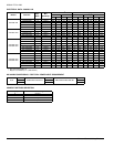
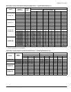
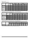
Electric Heaters - 4HK models shown under electrical data
include sequential operation and temperature dual limit
switches for safe, efficient operation. Circuit breakers are pro-
vided where shown.
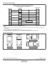
External Insulating Wrap Kit - Provides a vinyl covered ther-
mal insulation wrap, providing additional thermal insulation pro-
tection to prevent sweating in applications where extreme high
humidity is present. Air Handler cover (or wrap) has Velcro
edges for easy installation and access.
S1-1JV0117
S1-1JV0121
S1-1JV0124
S1-1JV0224 (SV* models only)
Humidstat - S1-2HU16700124
Control when used with ECM variable speed models will moni-
tor humidity level in both winter and summer seasons. Adjusts
blower speed and airflow provided to maintain desired humidity
levels.
LIMITATIONS
These units must be wired and installed in accordance with all
national and local safety codes.
Voltage limits are as follows:
Airflow must be within the minimum and maximum limits
approved for electric heat, evaporator coils and outdoor units.
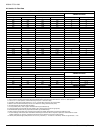
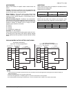
COOLING MODELS WITH ELECTRIC HEAT WIRING
* Optional dehumidification humidistat switch contacts open on humidity rise.
NOTES:
1. “Y/Y2” Terminal on air handler control board must be connected for full CFM and applications requiring 60 second blower off delay for
SEER enhancement.
2. Remove humidistat jumper on air handler control board.
3. For heat pump applications - set MODE jumper on air handler control board to the HP position.
4. To change quantity of heat during HP defrost cycle - reverse connections at W1 and W2 on air handler control board.
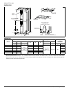
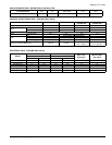
Air Handler Voltage Voltage code
1
Normal Operating
Voltage Range
1.Rated in accordance with ARI Standard 110, utilization range
“A”.
208/230-1-60 06 187-253
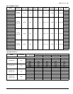
Entering Air Temperature Limits
Wet Bulb Temp.°F Dry Bulb Temp. °F
Min. Max. Min. Max.
57 72 65 95
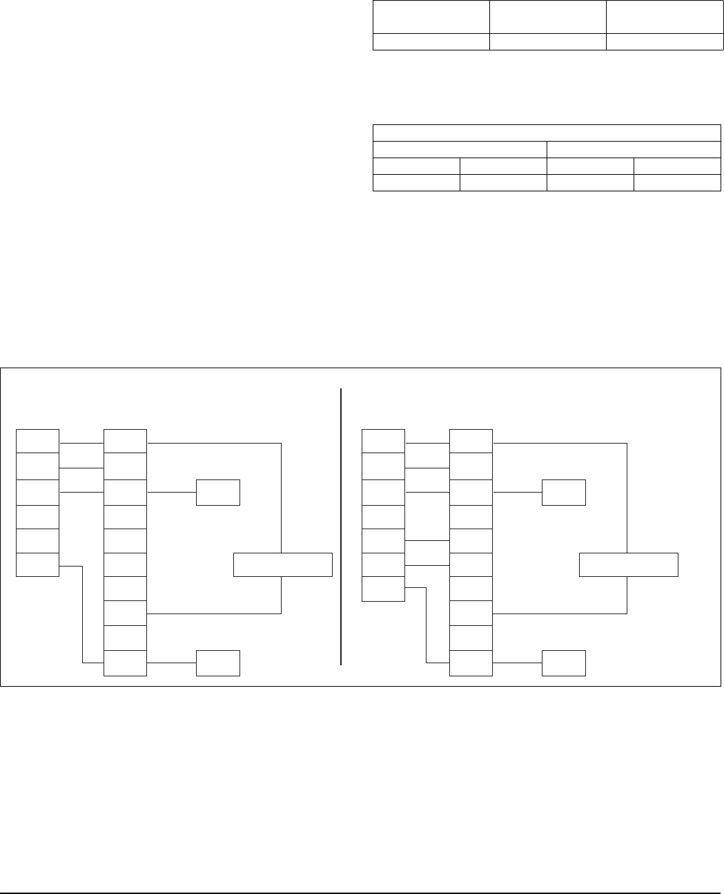
Air Handler Control Wiring
Typical A/C - Cooling only Applications
THERMOSTAT
AIR HANDLER
BOARD
1-STAGE
AIR CONDITIONING
RR
G
Y
W1
W2
C
G
W1
W2
Y
C
Y/Y2
Y1
O
HUM
X/L
COM
HUMIDISTAT
*
THERMOSTAT
AIR HANDLER
BOARD
1-STAGE
AIR CONDITIONING
RR
G
Y
W1
W2
C
G
W1
W2
Y
C
Y/Y2
Y1
O
HUM
X/L
COM
HUMIDISTAT
*
Air Handler Control Wiring
Typical A/C with Electric Heat Applications