


2 Johnson Controls Unitary Products
256819-YTG-J-1208
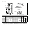
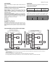
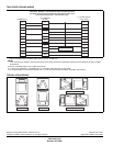
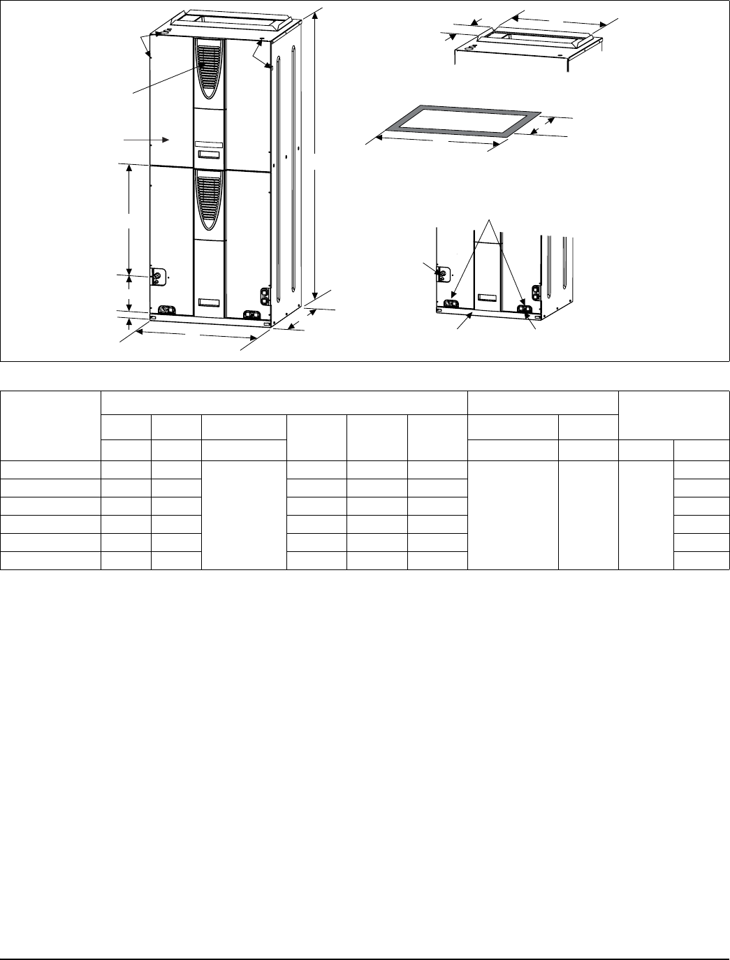
DIMENSIONS
10-3/8”
F
CIRCUIT
BREAKER
PANEL
BOTTOM INLET
DIMENSIONS
DRAIN PAN CONNECTIONS
FOR HORIZONTALAPPLICATIONS
BLOWER
COMPARTMENT
REFRIGERANT
CONNECTIONS
DRAIN CONNECTIONS
FOR UPFLOWAND
DOWNFLOWAPPLICATIONS
7-11/32”
D
B
A
C
1-1/2”
E
TOPOUTLET
DIMENSIONS
FILTER
ACCESS
18-9/32”
J
K
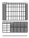
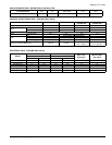
DIMENSIONS
Models
Dimensions (Inches)
Wiring Knockouts
1
Refrigerant
Connections
Line Size
AB C
DEF
JK
Height Width Depth Power Control Liquid Vapor
AVY24B**H21 46 17.5
21.5
(w/o cladding)
22.5
(with cladding)
12-3/8 13-29/32 14-19/32
7/8” (1/2”)
1 3/8” (1”)
1 23/32” (1 1/4”)
7/8” (1/2”) 3/8”
3/4”
AVY36C**H21 52 21 17-1/8 17-13/32 18-3/32 7/8”
AVY48D**H21 57 24.5 22-1/8 20-29/32 21-19/32 7/8”
SVY48D**N21 52 24.5 17-1/8 20-29/32 21-19/32 7/8”
AVY60D**H21 57 24.5 22-1/8 20-29/32 21-19/32 7/8’
SVY60D**N21 52 24.5 17-1/8 20-29/32 21-19/32 7/8”
1. Actual size (Conduit size).
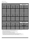
** Thermal expansion device indicators - “2_” indicates R-22 TXV is factory installed, “3X” indicates unit is a “Flex Coil” models with a field installed
R-22 or R-410A TXV, and “4_” indicates R-410A TXV is factory installed. Letter indicates TXV size as required, see outdoor unit technical infor-
mation for proper matches and requirements.