


POWER AND CONTROL WIRING
Field wiring to the unit must conform to provisions of the current
N.E.C. ANSI/NFPA No. 70 or C.E.C. and/or local ordinances.
The unit must be electrically grounded in accordance with local
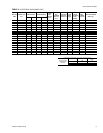
codes or,in their absence, with the N.E.C./C.E.C. Voltagetoler
-
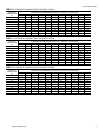
ances which must be maintained at the compressor terminals
during starting and running conditions are indicated on the unit
Rating Plate and Table 3.
The wiring entering the cabinet must be provided with me
-
chanical strain relief.
A fused or HACR breaker disconnect switch should be field pro
-
vided for the unit. If any of the wire supplied with the unit must be
replaced, replacement wire must be of the type shown on the wir
-
ing diagram.
Electrical line must be sized properly to carry the load. Each
unit must be wired with a separate branch circuit fed directly
from the meter panel and properly fused.
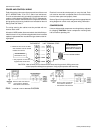
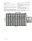
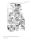
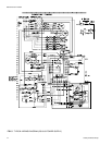
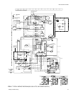
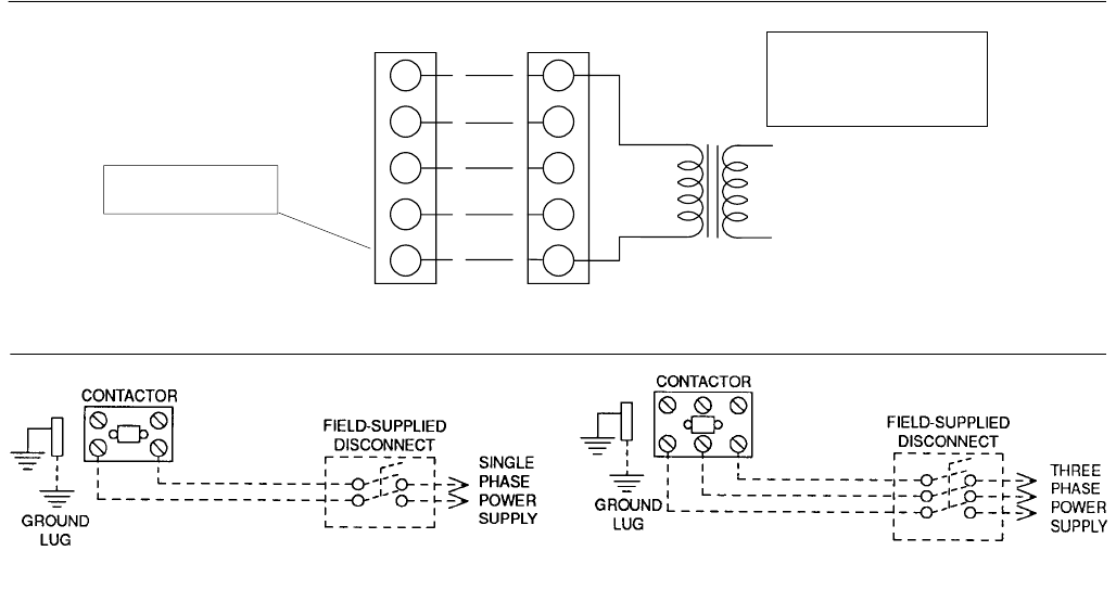
Refer to Figure 2 for typical field wiring and to the appropriate unit
wiring diagram for control circuit and power wiring information.
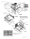
COMPRESSORS
Units areshippedwithcompressormountingsfactory-adjusted
for shipping. CAUTION: Loosen compressor mounting bolts
half turn before operating unit.
035-16703-001-A-0202
4 Unitary Products Group
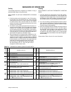
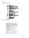
FIG. 2 - TYPICAL FIELD WIRING DIAGRAM
POWER WIRING
R
G
W
R
G
C
YY
W
C
24 VOLT TRANSFORMER
UNIT TERMINAL STRIP
THERMOSTAT
NOTE:
HEAT ANTICIPATOR
SHOULD BE SET AT 0.25
AMPS FOR ALL MODELS.
CAUTION: Label all wires prior to disconnection when servicing controls. Wiring errors can
cause improper anddangerousoperation.Verifyproperoperation after servicing.
PROGRAMMABLE
THERMOSTAT ONLY
CONTROL WIRING
** = Minimum wire size of 18 AWG
wire should be used for all field
installed 24 volt wire.
**
*
* = Only required on units with
supplemental electric heat.
REFER TO ELECTRICAL DATA
TABLES TO SIZE THE DISCON
-
NECT SWITCH, WIRING &
OVERCURRENT PROTECTION.
REFER TO ELECTRICAL DATA
TABLES TO SIZE THE DISCON
-
NECT SWITCH, WIRING &
OVERCURRENT PROTECTION.