


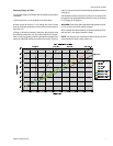
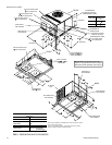
CLEARANCES
All units require certain clearances for proper operation and
service. Refer to Figure 3 for the clearances required for com
-
bustion, construction, servicing and proper unit operation.
WARNING:Do not permit overhanging structures or shrubs to
obstruct the condenser air discharge outlet.
DUCT WORK
These units are adaptable to downflow use as well as rear sup
-
ply and return air duct openings. To convert to downflow, use
the following steps:
1. Remove the duct covers found in the bottom return and
supply air duct openings. There are four (4) screws secur
-
ing each duct cover (save these screws to use later).
2. Install the duct covers, removed instepone,totherearsup
-
ply and return air duct openings. Secure with the four (4)
screws used in step one.
3. Seal the duct covers with silicone caulking.
Downflow units must have an L-shaped supply duct without
any outlets or registers located directly below the supply outlet
of the unit.
Duct work should be designed and sized according to the
methods of the Air Conditioning Contractors of America
(ACCA), as set forth in their Manual D.
A closed return duct system shall be used. This shall not pre-
clude use of economizers or ventilation air intake. Flexible
joints may be used in the supply and return duct work to mini-
mize the transmission of noise.
CAUTION: When fastening duct work to the side duct flanges on
the unit, insert the screws through the duct flanges only.
DO NOT insert the screws through the casing. Outdoor
duct work must be insulated and waterproofed.
NOTE: Be sure to note supply and return openings.
Refer to Figure 3 for information concerning rear and bottom
supply and return air duct openings.
FILTERS
Single phase units are shipped without a filter and is the responsi
-
bility of the installer to secure a filter in the return air ductwork or
install a Filter/Frame Kit (1FF0114).
A filter rack and a filters are standard on three phase units.
Filters must always be used and must be kept clean. When fil
-
ters become dirt laden, insufficient air will be delivered by the
blower, decreasing your units efficiency and increasing operat
-
ing costs and wear-and-tear on the unit and controls.
Filters should be checked monthly especially since this unit
may be used for both heating and cooling.
CONDENSATE DRAIN
A condensate trap is required to be installed in the condensate
drain. The plumbing must conform to local codes. Use a seal
-
ing compound on male pipe threads. Install the condensate
drain line (
“ NPTF) to spill into an open drain.
SERVICE ACCESS
Access to all serviceable componentsis provided by the follow
-
ing removable panels:
• Blower service access
• Electrical/filter access
• Compressor service access
Refer to Figure 3 for location of these access panels and mini-
mum clearance.
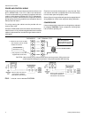
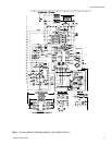
THERMOSTAT
The room thermostat should be located on an inside wall ap-
proximately 56" above the floor where it will not be subject to
drafts, sun exposure or heat from electrical fixtures or appli
-
ances. Follow manufacturer's instructions enclosed with the
thermostat for general installation procedure. Four or five color
coded insulated wires (minimum #18 AWG) should be used to
connect thermostat to unit. See Figure 2.
035-16703-001-A-0202
Unitary Products Group 3
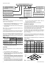
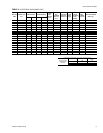
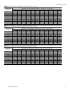
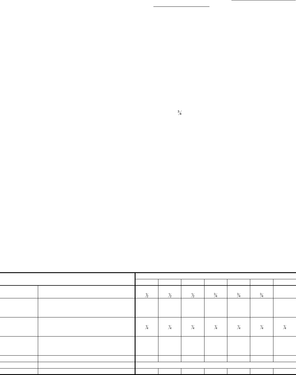
MODELS
DEB
018 024 030 036 042 048 060
EVAPORATOR
BLOWER
CENTRIFUGAL BLOWER (Dia. x Wd. in.) 9 X 6 10 X 8 10 X 8 10 x 8 11 X 10 11 x 10 11 x 10
FAN MOTOR HP (Three Speed)
1
EVAPORATOR
COIL
ROWS DEEP 2222223
FINS PER INCH 13 15 15 15 15 13 16
FACE AREA (Sq. Ft.) 2.19 2.81 4.38 4.38 4.38 5.62 5.26
CONDENSER
FAN
PROPELLER DIA. (in.) 22 22 22 22 22 22 22
FAN MOTOR HP
NOM. CFM TOTAL 1,800 2,200 2,400 2,400 2,400 2,800 2,800
CONDENSER
COIL
ROWS DEEP 1111111
FINS PER INCH 18 16 20 18 16 13 20
FACE AREA (Sq. Ft.) 8.3 8.3 8.3 8.3 11.7 16.4 16.4
CHARGE REFRIGERANT 22 (lbs./oz.) 3 / 4 3 / 5 3 / 13 3 / 10 4 / 7 5 / 15 5 / 15
FILTER FACE AREA (Sq. Ft. / Qty. / Size) 2.14 / 2 / 14" x 22"
COMPRESSOR HERMETIC Type, (Qty. = 1) Recip Recip Recip Recip Recip Scroll Scroll
TABLE 3 - PHYSICAL DATA