


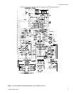
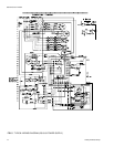
Cooling
The following sequences of operation are based on using a
standard single-stage cooling thermostat.
WITH POWER TO UNIT AND THERMOSTAT IN COOLING
MODE.
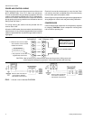
1. If the fan switch on the thermostat is in the “ON” position,
the 24 volts at “G” will energize the “K1" relay on the fan
control board, close the ”K1" relay contacts, and energize
the indoor blower motor. If the fan switch is in the “AUTO”
position, the blower will operate only when there is a call for
cooling by the thermostat.
2. On a call for cooling, the thermostat will send 24 volts to “Y”
on the fan control board. The 24 volt signal will energize
contactor “M1", and power will be supplied to the compres
-
sor and outdoor fan motor. If the fan switch on the thermo
-
stat is on the ”AUTO" position, the thermostat will also send
a 24 volt signal to “G” on the fan control board and the in
-
door blower will operate as indicated in step 1.
3. When the demand for cooling has been satisfied, the “M1"
contactor will be de-energized when the 24 volt ”Y" signal is
removed. If the fan switch on the thermostat is energized
when the 24 volt “Y” signal is removed. If the fan switch on
the thermostat is in the “ON” position, the indoor blower will
continue to run. If the fan switch is in the “AUTO”posi-
tion, the 24 volt “G” signal will be removed, and after a
60 second delay, the “K1" relay will open and de-
energize the indoor blower motor,
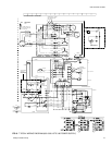
Heating
WITH POWER TO UNIT AND THERMOSTAT IN HEATING
MODE.
1. If the fan switch on the thermostat is in the “ON” position,
the 24 volts at “G” will energize the “K1" relay contacts, and
energize the indoor blower motor. If the fan switch on the
thermostat is in the ”AUTO" position, the blower will oper
-
ate only when thereisacallforheatingby the thermostat.
2. On a call for heating, the thermostat will send 24 volts to
“W1" on the fan control board. The 24 volts signal will ener
-
gize relay ”K2" on the fan control board, and the first stage
of electric heat will be energized.
3. When the heating demand is satisfied, the electric heat will
be de-energized when the 24 volt “W1" and ”W2" signals
are removed. If the fan switch on the thermostat is in the
“ON” position, the indoor blower will continue to run. If the
fan switch is in the “AUTO” position, the “K1" relay will open
and de-energize the indoor blowermotoraftertheappropri
-
ate time delay.
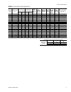
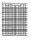
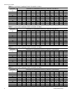
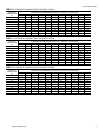
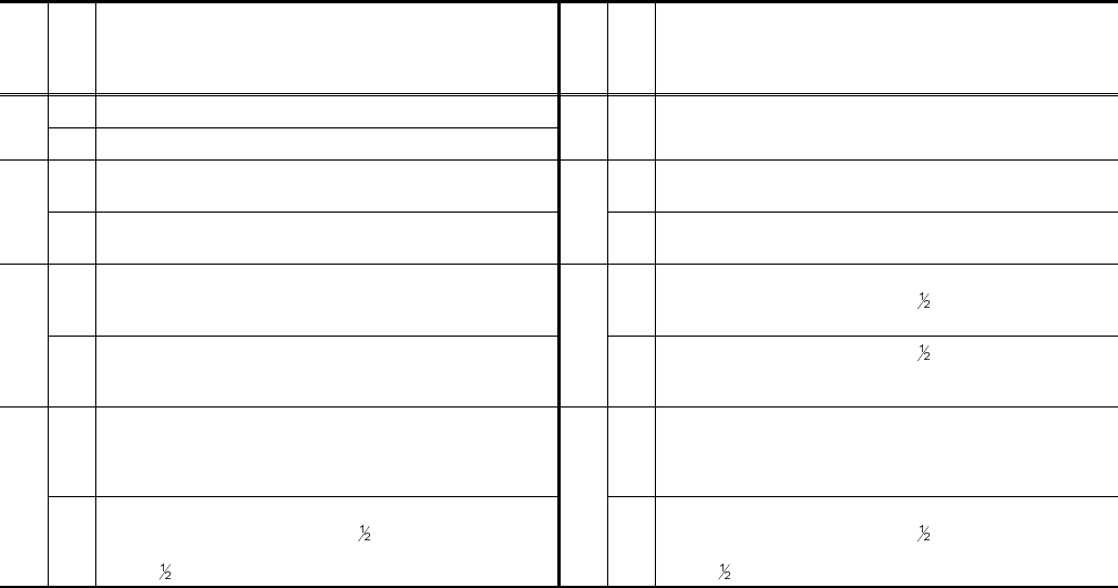
Please refer to Table 13 and 14 for more information.
Unitary Products Group 11
035-16703-001-A-0202
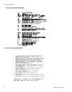
SEQUENCE OF OPERATION
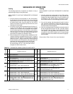
TABLE 13 - THERMOSTAT SIGNALS (SINGLE PHASE UNITS)
SIGNAL
STATE
BOARD FUNCTION
SIGNAL
STATE
BOARD FUNCTION
“G”
ON FAN INSTANT ON
OFF FAN INSTANT OFF
“G”
“Y”
ON
FAN INSTANT ON
COMPRESSOR AND OUTDOOR FAN INSTANT ON
“W1"
ON
FAN INSTANT ON
HEATER BANK 1 ELEC. HEAT INSTANT ON
OFF
COMPRESSOR AND OUTDOOR FAN INSTANT OFF
FAN 60 SECOND DELAY OFF
OFF
HEATER BANK 1 ELEC. HEAT INSTANT OFF
FAN 5 SECOND DELAY OFF
“G”
“W1"
ON
FAN INSTANT ON
HEATER BANK 1 ELEC. HEAT INSTANT ON
”W2"
ON
FAN INSTANT ON
HEATER BANK 1 ELEC. HEAT
SEC. DELAY OFF
HEATER BANK 2 ELEC. HEAT INSTANT ON
OFF
HEATER BANK 1 ELEC. HEAT INSTANT OFF
FAN 5 SECOND DELAY OFF
OFF
HEATER BANK 1 ELEC. HEAT
SEC. DELAY OFF
HEATER BANK 2 ELEC. HEAT INSTANT OFF
FAN 5 SECOND DELAY OFF
“G”
“W1"
”W2"
ON
FAN INSTANT ON
HEATER BANK 1 ELEC. HEAT INSTANT ON
HEATER BANK 2 ELEC. HEAT 10 SECOND DELAY ON
HEATER BANK 3 ELEC. HEAT 20 SECOND DELAY ON
“W1"
”W2"
ON
FAN INSTANT ON
HEATER BANK 1 ELEC. HEAT INSTANT ON
HEATER BANK 2 ELEC. HEAT 10 SECOND DELAY ON
HEATER BANK 3 ELEC. HEAT 20 SECOND DELAY ON
OFF
HEATER BANK 1 ELEC. HEAT INSTANT OFF
HEATER BANK 2 ELEC. HEAT
SECOND DELAY ON
HEATER BANK 3 ELEC. HEAT 1 SECOND DELAY ON
FAN
6
SECOND DELAY OFF
OFF
STAGE 1 ELEC. HEAT INSTANT OFF
HEATER BANK 2 ELEC. HEAT
SECOND DELAY ON
HEATER BANK 3 ELEC. HEAT 1 SECOND DELAY ON
FAN
6
SECOND DELAY OFF