


279104-YTG-B-0307
2 Unitary Products Group
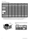
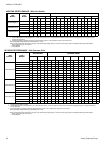
All dimensions are in inches. They are subject to change
without notice. Certified dimensions will be provided upon
request.
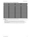
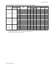
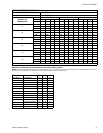
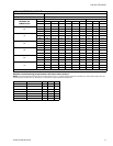
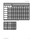
Physical and Electrical Data
MODEL E1RA036S25 E2RA048S25 E1RA060S25 E1RA036S46 E2RA048S46 E1RA060S46
Unit Supply Voltage
208/230-3-60 460 - 3 - 60
Normal Voltage Range
1
187 to 252 432 to 504
Minimum Circuit Ampacity 15.0 18.9 24.5 8.0 10.1 12.0
Max. Qvercurrent Device Amps
2
25 30 40 15 15 20
Compressor Type
3
Inertia
Scroll
D
Scroll
C
Inertia
Scroll
D
Scroll
C
Compressor Amps Rated Load 10.9 14.1 18.6 5.8 7.0 9.0
Locked Rotor 78 125 128 40 55 63
Crankcase Heater Yes No No Yes No No
Fan Motor Amps Rated Load 1.4 1.3 1.3 .8 .7 .8
Fan Diameter Inches 18 22 24 18 22 24
Fan Motor Rated HP 1/4 1/4 1/4 1/4 1/5 1/4
Nominal RPM 1,100 850 850 1,100 825 850
Nominal CFM 2,750 3,500 3,100 2,750 3,500 3,100
Coil Face Area Sq. Ft. 12.58 19.65 18.00 12.58 19.65 18.00
Rows Deep 112112
Fin / Inches 14 13 14 14 13 14
Liquid Line Set OD (Field Installed) 3/8 3/8 3/8 3/8 3/8 3/8
Vapor Line Set OD (Field Installed) 3/4 7/8 7/8 3/4 7/8 7/8
Unit Charge (Lbs. - Oz.)
4
5 - 12 8 - 3 11 - 3 5 - 12 8 - 3 11 - 3
Charge Per Foot, Oz. .68 .70 .70 .68 .70 .70
Operating Weight Lbs. 178 232 243 178 232 243
1. Rated in accordance with ARI Standard 110, utilization range “A”.
2. Dual element fuses or HACR circuit breaker.
3. All scrolls listed with a superscript “D” are Danfoss scrolls. All scrolls listed with a superscript “C” are Copeland scrolls.
4. The Unit Charge is correct for the outdoor unit, matched indoor coil and 15 feet of refrigerant tubing. For tubing lengths other than
15 feet, add or subtract the amount of refrigerant, using the difference in length multiplied by the per foot value.
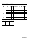
C
A
B
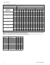
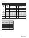
DIMENSIONS
Unit
Model
Dimensions
(Inches)
Refrigerant
Connection
Service Valve Size
A
1
1. Including fan guard.
B C Liquid Vapor
036 25 35 23
3/8”
3/4”
048 33 37 27 7/8”
060 26 43 32 7/8”