


Start-Up Procedure
Start the furnace using the procedures in section
Operating Your Furnace on pages 15 through 19.
WARNING
DANGER OF BODILY INJURY OR DEATH
LIQUEFIED PETROLEUM (L.E) GAS IS HEAVIER
THAN AIR AND IT WILL SETTLE IN ANY LOW
AREA, INCLUDING OPEN DEPRESSIONS AND IT
WILL REMAIN THERE UNLESS AREA IS
VENTILATED.
NEVER ATTEMPT START-UP OF UNIT BEFORE
THOROUGHLY VENTILATING AREA•
CHECK THE GAS INPUT (NATURAL GAS ONLY)
WARNING
NATURAL GAS HEATING VALUE (BTU PER CUBIC
FOOT) CAN VARY SIGNIFICANTLY, THEREFORE,
IT IS THE INSTALLER'S RESPONSIBILITY TO SEE
THAT BTU INPUT TO THE FURNACE ISADJUSTED
PROPERLY. FAILURE TO DO SO COULD CAUSE
HEAT EXCHANGER FAILURE, ASPHYXIATION, FIRE
OR EXPLOSION, RESULTING IN DAMAGE, BODILY
INJURY OR DEATH. REFER TO THE NATURAL
FUEL GAS CODE (NFPA-54) TO BE SURE THE FUR-
NACE IS BURNING FUEL AT THE PROPER RATE.
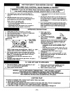
Check the furnace operation as outlined in the following
instructions• If any sparking, odors or unusual noises are
encountered, shut off electrical power immediately.
Recheck for wiring errors, or obstructions in or near op-
tional blower motor•
NOTICE:
During the initial firing of this unit some smoke and odor
may occur• We recommend ventilating the area during this
initial "break in period."
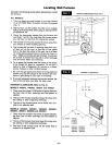
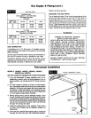
CHECK GASlNPUT AND PRESSURES
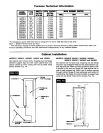
For furnace located at altitudes between sea level and
2000 feet, the measured input must not be greater than
the input shown on the rating plate of the furnace. For
elevations above 2000 feet, the measured input must not
exceed the input of the rating plate reduced by 4 percent
for each 1000 feet that the furnace is above sea level.
Gas supply pressure and manifold pressure with the
burners operating must also be as specified on the rating
plate.
TYPE OF GAS MANIFOLD PRESSURE, IN. W.C.
Natural 4
L.R 11
Rated input will be obtained on 2500 B'FU propane at 11
inches manifold pressure with factory-sized orifices. If L.R
Gas having a different heating value is supplied, orifices
must be changed by a qualified installer before the fur-
nace is operated•
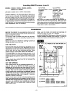
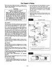
CHECK THE MANIFOLD GAS PRESSURE
A tapped opening isprovided in the gas valve to facilitate
measuring the manifold gas pressure. A "U Tube"
manometer having a scale range from 0 to 12 inches of
water should be used for this measurement. The manifold
pressure must be measured with the burner and pilot
operating. Any major changes in the flow must be made
bychanging the size ofthe burner orifice. Check with local
gas company for proper orifice size.
Underfiringcould cause inadequate heat, excessiveconden-
sation or ignition problems. Overfiring could cause soot-
ing flame impingement or overheating of heat exchanger•
Before starting natural gas input check, obtain heating
value of gas (BTU per cubic foot) at standard conditions
from your local supplier. This factor is used in "Check the
Gas Input" section and procedure.
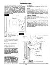
To measure the input using the gas meter, proceed as
follows:
Step 1: Turn off gas supply to all other appliances except
the furnace.
Step 2: With the furnace operating, time the smallest dial
on the meter for one complete revolution. If this
is a 2 cubic foot dial, divide the seconds by 2; if
it is a 1 cubic foot dial, use the time in seconds
as is. (3,600 = Sec. Per Hr.) This gives the
seconds per cubic foot of gas being delivered to
• the furnace.
Step 3:
Step 4:
Assumingnatural gas witha heating value of 1000
Btu per cubic foot and 34 seconds per cubic foot
as determined by step (2), then:
Input: 1,000X 3,600 + 34 = 106,000Btu PerHour
This measured input must not be greaterthan the
input indicated on the rating plate ofthe furnace.
Relight all other appliances turned off in step 1
above. Be sure all pilot burners are operating.
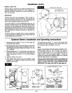
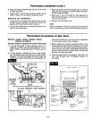
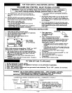
ADJUST PILOT BURNER
NOTE: Pilotgas may need adjustment depending on inlet
pressure, increase or decrease to obtain proper
setting.
Pilotflame should surround 3/8 inchto 112inch ofthe ther-
mocoupletip. Toadjust, if needed, remove pilotadjustment
cap (do not lose gasket).
1,
2.
Remove screw cover over pilot adjusting screw.
Insert small screwdriver. Adjust flame as needed. Turn
screw counterclockwise (I¢-_) to increase flame,
clockwise (_) to decrease.
3. Turnthermostatto highest setting. Main burners should
light quickly and smoothly. Turn thermostat to lowest
setting. Main burners should go out. Pilot should re-
main lighted.
4. Replace screw cover over pilot adjusting screw.
m14m