


Gas Supply & Piping
Gas control valve, within the furnace, is shipped with a
seal over gas inlet tapping. Do not remove this seal until
ready to connect piping.
WARNING
DANGER OF PROPERTY DAMAGE,
BODILY INJURY OR DEATH.
MAKE SURE THE FURNACE IS EQUIPPED TO
OPERATE ON THE TYPE OF GAS AVAILABLE.
MODELS DESIGNATED AS NATURAL GAS ARE TO
BE USED WITH NATURAL GAS ONLY. FURNACE
DESIGNATED FOR USE WITH LIQUEFIED
PETROLEUM (L.R) GAS HAVE ORIFICES SIZED
FOR COMMERCIALLY PURE PROPANE GAS.
THEY CANNOT BE USED WITH BUTANE OR A
MIXTURE OF BUTANE AND PROPANE.
GAS SUPP_
For Natural Gas, the minimum inlet gas supply pressure
for the purpose of input adjustment is 5" column. The max-
imum inlet gas supply pressure is 7" water column.
For L.R Gas, the minimum inlet gas supply pressure for
the purpose of input adjustment is 11" water column. The
maximum inlet gas supply pressure is 13" water column.
Gas pressures and input to the burners must not exceed
the rated input and pressure shown on the rating plate.
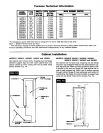
On Natural Gas the manifold pressure should be 4 inches
water column. The manifold pressure should be 11 inches
water column for L.R Gas. See page 13 for operation
above 2000 feet altitude. Orifice change may be required
to suit gas supplied. Check with your local gas supplier.
ORIFICE SIZES
Furnace Technical Information, page 13, shows the cor-
rect orifice sizes for the different input ratings when using
Natural or L.R Gas.
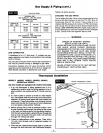
GAS PIPING
The gas supply line must be of adequate size to handle
the BTU/HR requirements and length of the run for the
unit being installed.
Determine the minimum pipe size from Fig. 10, page 11,
basing the length of the run from the gas meter or source
to the unit.
All piping must comply with local codes and ordinances
or with the National Fuel Gas Code (ANSI Z223.1 NFPA
No. 54), whichever applies.
IN Canada: Follow CAN/CGA-B149.1 (.2) Canadian
Standard.
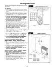
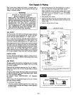
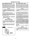
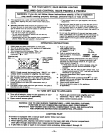
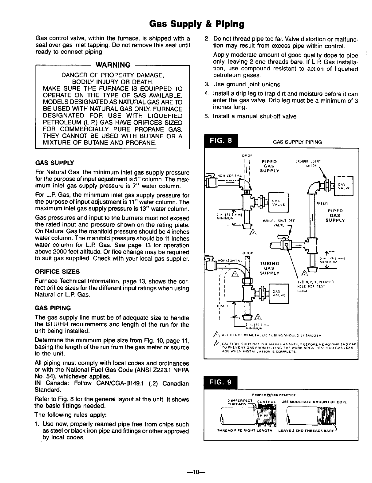
Refer to Fig. 8 for the general layout at the unit. It shows
the basic fittings needed.
The following rules apply:
1. Use new, properly reamed pipe free from chips such
as steel or black iron pipe and fittings or otherapproved
by local codes.
2,
3,
4.
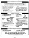
Do not thread pipe too far. Valve distortion or malfunc-
tion may result from excess pipe within control.
Apply moderate amount of good quality dope to pipe
only, leaving 2 end threads bare. If L.R Gas installa-
tion, use compound resistant to action of liquefied
petroleum gases.
Use ground joint unions.
Install a drip leg to trap dirt and moisture before it can
enter the gas valve. Drip leg must be a minimum of 3
inches long.
5. Install a manual shut-off valve.
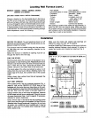
GAS SUPPLY PIPING
DROP
] I PIPED ;R0UN0 JOINT
I I GAS UNION
J_ SUPPLY
._;:_Hor ,ZONr AL i 'l ql,
RISER
l,_ 176 2 mini GAS
MiNiMUMor_oP__" UA_AS_SY_ANuAtSHUT OFF SUPPLY
_ 3 ,_ 1/6 _ r.nd
! ( SUPPLY \ l'X--
I ! GAUGE
I I
hi',se!,,
' I
I I
_/_ ALL BEttO5 iN M[TAL I.IC _ LJHING 514OULO B[ 5_,4OOTH
_" _.AklTION 511UT OyF [14[ M_IN _AS SUppI.y gEl'Oil[ N[MOVING Eft[) 12,_p
ro PN[VENT GAS FIt(IM FILLING Ttl[ WORK #.R_.A TE.ST _Ofl GAS L[AK
AGE WIt[N IIN_TAI LAIlON IS COMPI_ET[
PROPER PIPING PRACTICE
2 IMPERFECT CONTRO L USE MOOERATE AMOUNT OF DOP[
THREADS
--10n