


Installation (cont.)
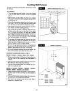
GAS AND ELECTRICAL SUPPLY OPENINGS
Holes must be drilled for the gas line (and electrical
supply if you use an optional Blower Kit). Drill a 1-1/2
inch hole in wall for gas line where indicated on
cardboard template or refer to Fig. 3, page 7. You will
have to determine whether the gas line will enter the
home through the outside wall or wall floor plate. These
instructions can only guide you in where the gas line
will enter the furnace.
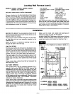
TEMPLATE
TEMPLATE
IMPORTANT
For walls more than 9 inches thick, read note below.
NOTE
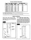
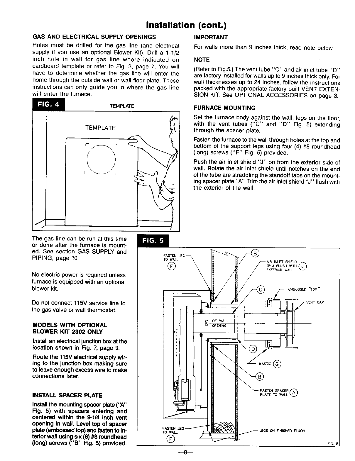
(Refer to Fig.5.) The vent tube "C" and air inlet tube "D"
are factory installed for walls up to 9 inches thick only. For
walt thicknesses up to 24 inches, follow the instructions
packed with the appropriate factory built VENT EXTEN-
SION KIT. See OPTIONAL ACCESSORIES on page 3.
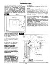
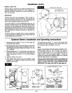
FURNACE MOUNTING
Set the furnace body against the wall, legs on the floor,
with the vent tubes ("C" and "D" Fig. 5) extending
through the spacer plate.
Fasten the furnace to the wall through holes at the top and
bottom of the support legs using four (4) #8 roundhead
(long) screws ("F" Fig. 5) provided.
Push the air inlet shield "J" on from the exterior side of
wall. Rotate the air inlet shield until notches on the end
of the tube are straddling the standoff tabs on the mount-
ing spacer plate "A". Trim the air inlet shield "J" flush with
the exterior of the wall.
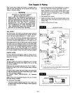
The gas line can be run at this time
or done after the furnace is mount-
ed. See section GAS SUPPLY and
PIPING, page 10.
No electric power is required unless
furnace is equipped with an optional
blower kit.
Do not connect 115V service line to
the gas valve or wall thermostat.
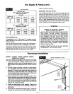
MODELS WITH OPTIONAL
BLOWER KIT 2302 ONLY
Install an electrical junction box at the
location shown in Fig. 7, page 9.
Route the 115V electrical supply wir-
ing to the junction box making sure
to leave enough excess wire to make
connections later.
INSTALL SPACER PLATE
Installthe mounting spacer plate ("A"
Fig. 5) with spacers entering and
centered within the 9-114 inch vent
opening in wall. Level top of spacer
plate (embossed top)and fastento in-
terior wall using six (6) #8 roundhead
(long) screws ("B" Fig. 5) provided.
FASIEN LE
TO WALL
©
FASTEN
TO WALL
®
INLET SHIELD
TRIM FLUSH Wl_r_
EX"[ZRIOR WALL Q
F EMBOSSED "TOP w
MAS_C(_
PLATE TO WALL (_
RG. 5
_8I