


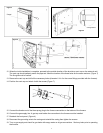
12. When the inside installation is complete, proceed to the outside location of the aluminium vent cap on the external wall.
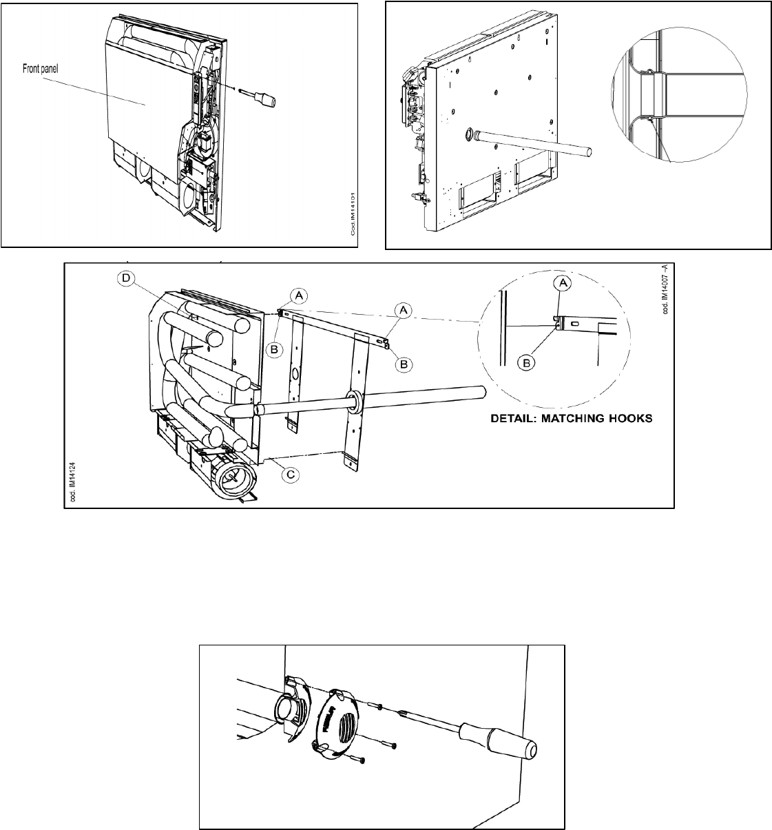
The vent cap should perfectly match the pipe end. Mark the location of the three holes for the screw anchors. (Figure 7)
The flue grid must be vertical.
13. Remove the vent cap and drill all the necessary holes (diameter 1/4 in. for the screw fittings provided with the furnace).
14. Position the vent cap and attach it with the screws (Figure 7).
15. Connect the female end of the three-prong plug to the furnace connection on the bottom of the furnace.
16. Connect the gas supply line. A gas tap must before the connection to the furnace must be installed.
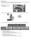
17. Reattach the front panel. (Figure 4)
18. Reconnect the grounding wire to the casing and reinstall the casing then tighten the screws.
19. Turn on gas supply and check for gas leaks with soapy water on all gas connections. Seal any leaks prior to operating
the furnace.
Figure 4
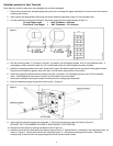
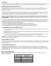
Figure 5
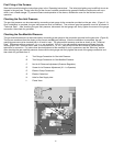
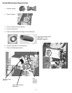
O-Ring Gasket
Figure 6
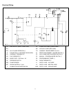
7