


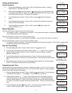
First Firing of the Furnace
Start the furnace following the instructions given in the “Operating Instructions“. The initial pilot lighting may be difficult due to air
trapped in the gas lines. During initial firing of the furnace, residual manufacturing grease will bake-out and smoke will occur
which is not a health danger. To prevent nuisance and operation of fire alarms, ventilate the room for the first two hours of
operation.
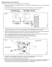
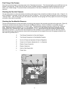
Checking the Gas Inlet Pressure
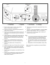
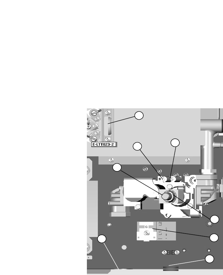
The gas inlet pressure can be measured by connecting a test gauge to the connection provided on the gas valve. (Figure 8 - A)
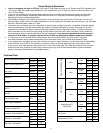
Once installation is complete, the gas inlet pressure must be checked. The minimum gas inlet pressure must be as shown in
“Technical Data”. After checking the gas inlet pressure, disconnect the test gauge and firmly tighten the screw of the gauge
connection, then check for gas leaks.
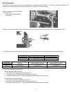
Checking the Gas Manifold Pressure
The gas manifold pressure can be measured by connecting a test gauge to the connection provided on the gas valve. (Figure 8).
The furnace comes set from the factory at the correct manifold gas pressure. After the installation is completed, the gas
manifold pressure must be checked both in Hi and Lo input. The gas manifold pressure must be as shown in the “Technical
Data”. Differences of plus or minus 0.1 in. w.c. are accepted. If the Hi or Lo gas manifold pressures are different from the
values given in the “Technical Data” table, or are more than 0.1 in. w.c., shut off the furnace and contact a qualified service
technician for correction. For instructions about adjustment of the manifold Hi and Lo pressures, see the “Servicing” section.
After checking the gas manifold pressure, disconnect the test gauge and firmly tighten the screw of the gauge connection and
then check for gas leaks from it.
9
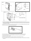
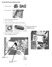
A Test Gauge Connection for Gas Inlet Pressure
B Test Gauge Connection for Gas Manifold Pressure
C Nut for Hi Pressure Adjustment (Pressure Regulator)
D Screw for Lo Pressure Adjustment (Hi – Lo Operator)
E Electric Clamp Connection
G Electric Cable Inlet
H Hole for Gas Supply Inlet
L Flame View
A
B
C
D
E
G
H
L
10