


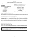
Outside Location for Vent Terminal
Upon delivery, check to make sure the packaging has not been damaged.
1. Remove the furnace from box/packaging taking care not to damage the paper template to be used to mark the holes for
mounting the furnace.
2. After marking the appropriate holes using the above mentioned template, make a 2-inch diameter hole.
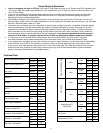
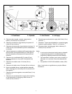
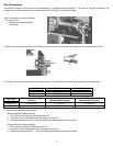
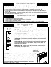
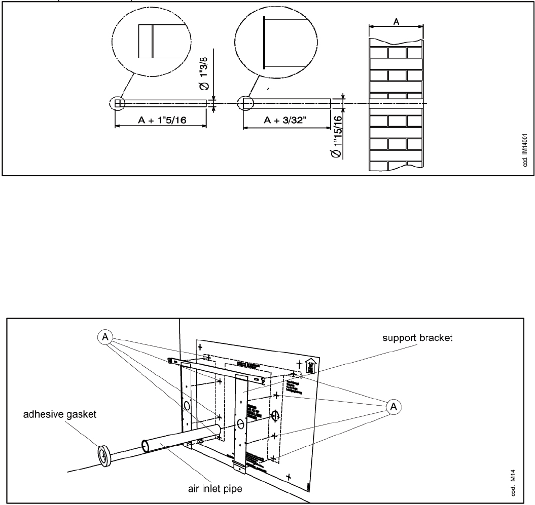
3. Cut the combustion exhaust and fresh air inlet tubes according to the wall thickness (Figure 2):
Air Inlet Tube Length = Wall Thickness + 3/32-inch
F Flue Outlet Tube Length = Wall Thickness + 1-5/16 inches
A + 33.3 mm
A
+ 2.3 mm
Ø 49.2
Figure 2
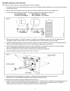
4. Drill the mounting holes “A” (8 holes) in the wall. If possible, use self-tapping screws, drill 1/8-inch diameter holes. If
self-tapping screws cannot be used, drill 1/4-inch diameter holes and use the plastic anchors provided.
5. Install the supporting bracket to the wall; insert the air pipe in the wall through the hole provided in the support bracket.
Place the round adhesive gasket around the hole, so that the air pipe remains in its position.
6. Attach the supporting bracket with the screws provided. If possible, use self-tapping screws, drill 1/8-inch diameter
holes. If self-tapping screws cannot be used, use the plastic anchors provided.
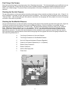
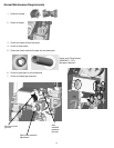
7. Remove the casing loosening the screws and disconnect the casing grounding cable.
8. Place the adhesive spongy lining behind the furnace. (Figure 3)
Figure 3
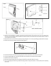
9. Attach the flue exhaust flue pipe end (diameter 1” 3/8) on the furnace pipe male connection (Figure 5).
BE SURE THAT THE RUBBER SILICONE O–RING GASKET IS IN POSITION.
10. Remove the front panel by loosing the lateral screws (Figure 4).
11. Install the furnace to the wall leaning the bottom edge of panel “C” (where the fan is located) on the supporting frame, as
shown in Figure 6. Attach the furnace to the matching hooks “A”, with light pressure against the wall). Install the
heating body of the furnace to the supporting bracket with the two lateral screws.
6